Checking input control signal
1. Install a volt meter to the ground pin connection and to the signal pin.
2. Turn the power on for the electrical controller.
3. Actuate the electrical controller and read the voltage.
4. The control voltage should be per the electrical controller output range.
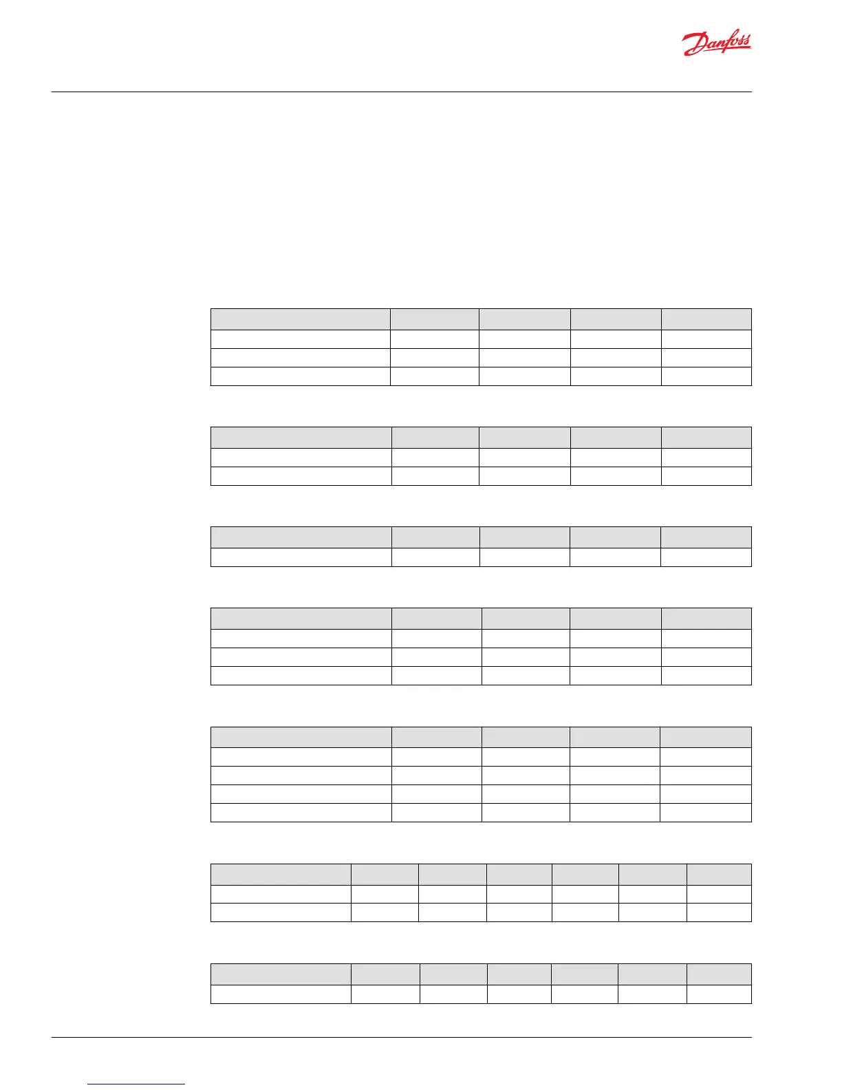
PVE Series 4/7 Connectors
PVEO/PVEO-R/PVEO-HP
Connector Pin 1 Pin 2 Pin 3 Pin 4
1x4 AMP Udc_A Udc_B GND GND
1x4 DEU Udc_A GND GND Udc_B
1x4 DIN Udc_A Udc_B GND
PVEO-DI
Connector Pin 1 Pin 2 Pin 3 Pin 4
2x4 AMP (A) Udc_A Udc_B GND GND
2x4 AMP (B) DI-B DI-A GND Udc
2
PVEM
Connector Pin 1 Pin 2 Pin 3 Pin 4
1x4 DIN Udc Us Error GND
PVEA/PVEH/PVES
Connector Pin 1 Pin 2 Pin 3 Pin 4
1x4 AMP Us Udc GND Error
1x4 DEU Us Error GND Udc
1x4 DIN Udc Us Error GND
PVEA-DI/PVEH-DI
Connector Pin 1 Pin 2 Pin 3 Pin 4
2x4 AMP (A) Us Udc GND Error
2x4 AMP (B) DI-A DI-B GND Udc
2
2x4 DEU (A) Us Error GND Udc
2x4 DEU (B) Udc
2
GND DI-A DI-B
PVEH-FLA
Connector Pin 1 Pin 2 Pin 3 Pin 4 Pin 5 Pin 6
1x6 AMP Us Udc GND Error Float
1x6 DEU Us Error Float GND Udc
PVEH-SP/PVES-SP
Connector Pin 1 Pin 2 Pin 3 Pin 4 Pin 5 Pin 6
1x6 DEU Us Error SP GND Udc
Service Manual
PVG 32 Proportional Valve Group
PVG 32 Component Troubleshooting
40 |
©
Danfoss | February 2017 11039167 | AX00000031en-US0301
 Loading...


