Required tools
The service procedures described in this manual can be performed using common mechanic’s hand
tools. Special tools, if required, are shown. When testing system pressures, calibrate pressure gauges
frequently to ensure accuracy. Use snubbers to protect gauges.
Port locations and gauge installation
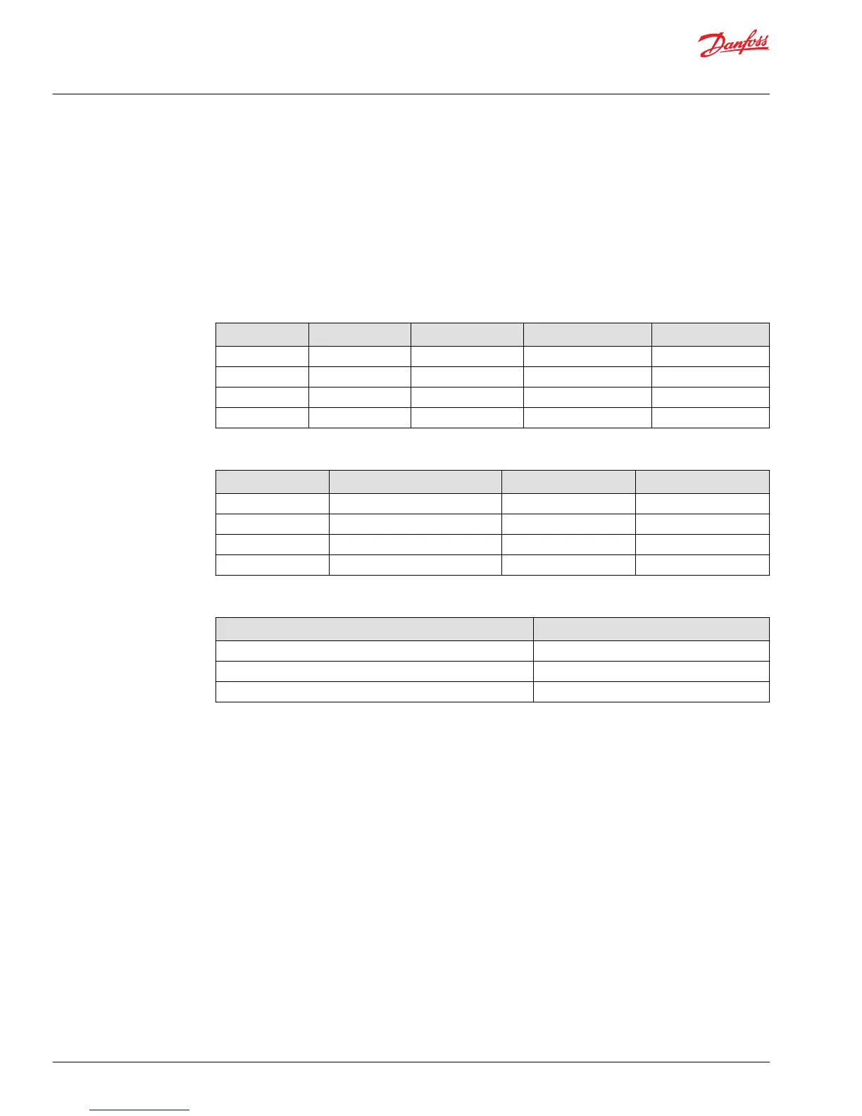
The following tables and drawing show the port locations and gauge sizes needed.
Port information
Port identifier Port size Wrench size Pressure obtained Gauge size, bar [psi]
L1, L2 1-1/16 12 SAE 9/16 internal hex Case drain 10 [150]
MA, MB 9/16 18 SAE 11/16 hex System pressure 600 [9,000]
M3 9/16 18 UNF 11/16 hex Charge pressure 50 [750]
M4, M5 9/16 18 SAE 11/16 hex Servo pressure 50 [750]
System valves
Port identifier Relief Port size Wrench size
RA A port pressure relief valve 1-5/16 12 UNF 1-1/4 hex
RB B port pressure relief valve 1-5/16 12 UNF 1-1/4 hex
R Charge pressure relief valve 3/4 16 UNF 7/8 hex
BP Bypass valve 5/8 18 UNF 1 inch hex
System ports
Port identifier Port size
A system pressure port 1-5/16 12 SAE
B system pressure port 1-5/16 12 SAE
S (charge pressure inlet) 1-5/16 12 SAE
Service Manual
Series 40 M46 Variable Pumps
Required tools and pressure measurements
12 |
©
Danfoss | September 2017 11026743 | AX00000027en-US0202

 Loading...


