24 of 114
M-AP-001-EN Rev. Q
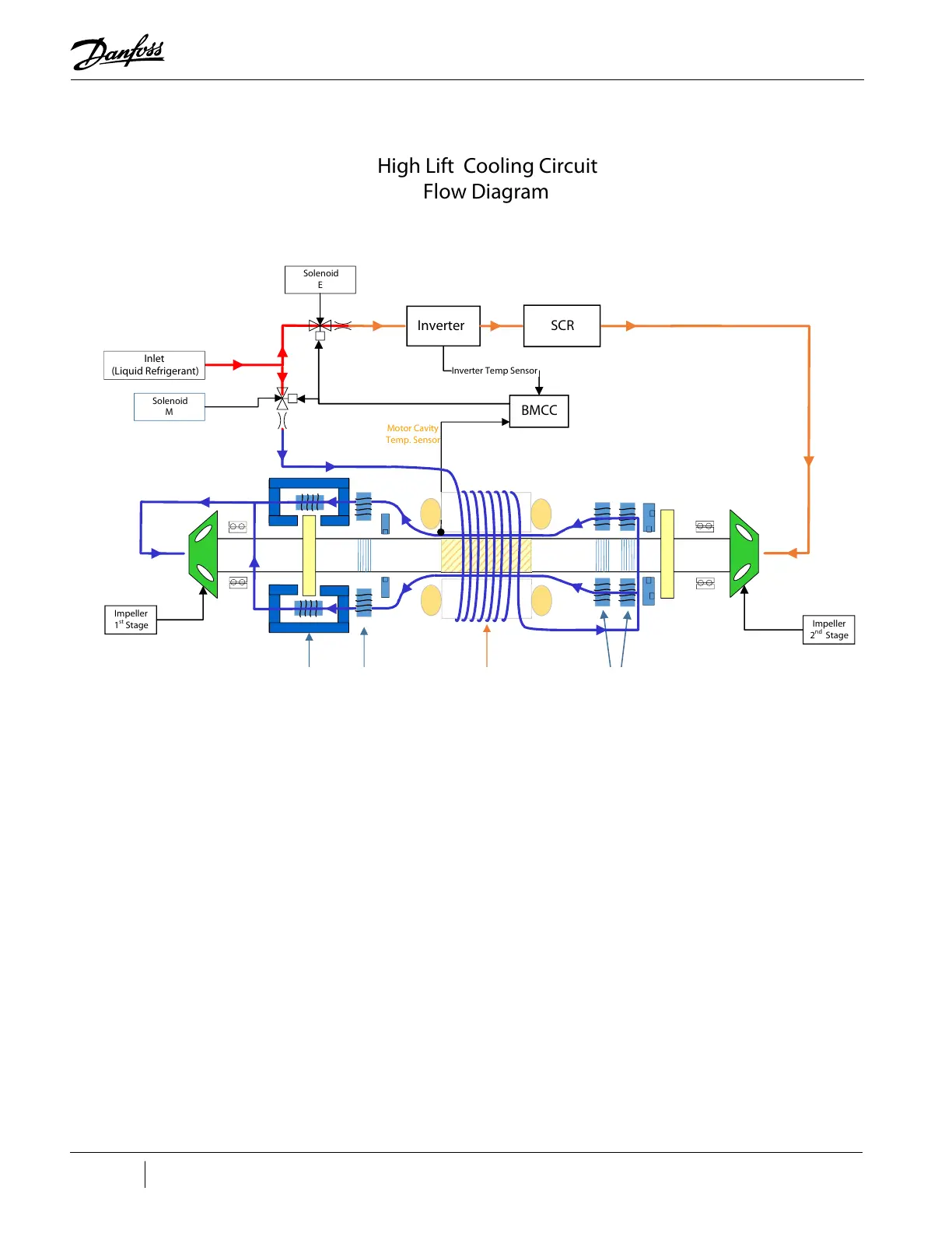
Figure 3-5 Compressor Cooling Circuit (TGH285 / TTH375)
3.3 Inlet Guide Vanes
The Inlet Guide Vane (IGV) assembly is a variable-angle guiding device that is used for capacity control.
The IGV assembly consists of movable vanes and a motor. The vane opening is determined by the
BMCC and controlled by the Serial Driver. The IGV position can vary between 0-110% where 0% is fully
closed and 110% is fully open with the vanes at a 90° angle.
3.4 Compressor Control Overview
Refer to "Figure 3-6 Compressor Control System Functional Block Diagram" which shows a functional
block diagram of the compressor control and monitoring system. Refer to "Figure 3-8 Magnetic
Bearing Control System" which displays the component locations. The major components include:
• Motor Drive
• Soft-Start Board
• Bearing Motor Compressor Controller (BMCC)
• Bearing PWM Amplifier
• Backplane
• Serial Driver
• HV DC-DC Converter
High Lift Cooling Circuit
Flow Diagram
Inverter
SCR
BMCC
Inlet
(Liquid Refrigerant)
Inverter Temp Sensor
Impeller
1
st
Stage
Impeller
2
nd
Stage
Radial
Bearing
Axial Bearing
Stator/Rotor
Radial
Bearing
Solenoid
E
Solenoid
M
Motor Cavity
Temp. Sensor