Danfoss Heating
5
GB
PL
GR
ES
GB
1.1 Installation
• Remove wallplate from unit by unscrewing the two screws on
the bottom edge of the unit.
• From the top left hand corner of the wallplate, there must be
clearances of at least 140 mm to the right, 15mm to the left,
30mm above and 100mm below in order to mount the plug-on
module.
• The wallplate must be securely mounted either directly to the
wall using suitable wood screws or to a fl ush mounted 1-gang
electrical accessory box using M3.5 screws.
• Cable access can either be from behind for concealed cabling, or
from below for surface cabling. If surface cable is used, cut out
cable access slot on plug-on module prior to mounting.
• For wiring connections refer to diagram on page 7.
The TP9000 is double insulated and does not require an earth
connection, however a parking terminal is provided on the
wallplate. This is clearly marked with an Earth symbol.
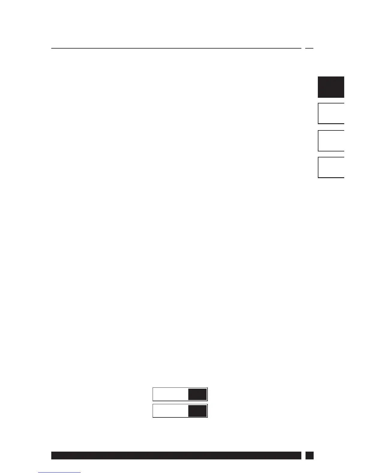
• Prior to mounting the plug-on module, DIL switches on the
rear of the plug-on module must be set. See diagram below for
available options.
• Mount plug-on module to wallplate by locating tabs on top of
wallplate in apertures on rear of module, hinge down and press
fi rmly to wallplate before tightening securing screws on bottom
of wallplate.
1
2
Keyboard disabled
Reset disabled Reset enabled
Keyboard enabled
OFF
ON
Sw. No.
Prior to mounting the unit the 2 DIL switches on the rear of the
unit have to be moved to the required position. The factory
presets are shown below.
 Loading...