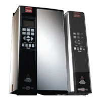
VLT® 5000 Crane
General aspects of EMC emissions ..................................114
H
High Voltage Test.......................................................... 30
Hoist direction
.............................................................. 74
I
IT mains...................................................................... 33
Infinitely Variable Change of NumericData Value
................... 40
Input
............................................................................ 6
Installation of Brake Resistor Temperature Switch
................ 29
Installation of Control Cables
........................................... 28
Installation of Motor Cables
............................................. 28
Installation of Relay Terminals
........................................... 29
Intermediate circuit
........................................................ 12
Ironloss resistance
........................................................ 57
J
Jog frequency .............................................................. 59
Jog ramp time
.............................................................. 58
L
Lower limit .................................................................109
Language
.................................................................... 50
LCP copy
.................................................................... 50
LCP JOGGING
............................................................. 52
LCP reset of trip
........................................................... 53
LCP reversing
.............................................................. 52
LCP stop
.................................................................... 52
LEDs
.......................................................................... 37
Live Zero Funct
............................................................ 64
Load high
.................................................................... 74
Load low
..................................................................... 74
Load monitoring
........................................................... 74
Local control
................................................................ 43
Local reference
............................................................. 50
Local/Remote Operation
................................................. 50
Low speed at error
........................................................ 74
Low speed reference current
........................................... 60
M
Main Reactance ........................................................... 56
Mains supply
............................................................... 16
Mains Supply Interference/Harmonics
...............................114
Manual initialization
........................................................ 40
Maximum reference
....................................................... 58
Mean radius 1
.............................................................. 75
Mean radius 2
.............................................................. 76
Mechanical brake off delay
.............................................. 75
Mechanical brake on delay
.............................................. 75
Mechanical speed N1
.................................................... 76
Mechanical speed N2
.................................................... 76
Mechanical speed N3
.................................................... 77
Mechanical speed N4
.................................................... 77
Mechanical speed N5
.................................................... 77
Mechanical speed N6
.................................................... 77
Mechanical speed N7
............................................... 78, 78
Minor Interference on Mains
............................................ 13
Miscellaneous
................................................................ 7
Missing motor phase
.................................................... 59
Motor
........................................................................... 7
Motor current
............................................................... 54
Motor frequency
........................................................... 54
Motor power
................................................................ 54
Motor Thermal Protection
.......................................... 30, 55
Motor voltage
............................................................... 54
N
Name........................................................................108
Nameplate data
............................................................ 72
NO/NC
......................................................................... 6
Number of elements
.....................................................106
O
Operating Data............................................................. 70
Operating mode
........................................................... 71
Operating Status at Local Operation
.................................. 11
Operating Status at Remote Control
.................................. 10
Ordering Numbers, Compact
..........................................118
Output
......................................................................... 6
Output speed high limit
.................................................. 58
P
Password Protection ................................................ 42, 73
Phase Loss Monitor
....................................................... 60
Pole number
................................................................ 57
Power at N1
................................................................ 76
Power at N2
................................................................ 77
Power at N3
................................................................ 77
Power at N4
................................................................ 77
Power at N5
................................................................ 77
Power at N6
................................................................ 77
Power Factor
..............................................................114
Power limit function
....................................................... 76
Power Loss N1
............................................................ 78
Power Loss N2
............................................................ 78
Power Loss N3
............................................................ 78
Power Loss N4
............................................................ 78
Power Loss N5
............................................................ 78
Power Loss N6
............................................................ 78
Power Loss N7
............................................................ 78
MG.50.N4.02 - VLT is a registered Danfoss trademark
120
 Loading...


