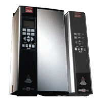
VLT® 5000 Crane
Appendix
A
Accuracy of Display Readout........................................... 18
Actual Output Speed
....................................................103
Additional characteristics
...............................................109
Additional Text
.............................................................110
Address
...................................................................... 82
Advanced VLT Protection
................................................ 13
Advanced Motor Protection
............................................. 13
AI (mA) 60 Funct.
.......................................................... 63
AI 53 Funct.
................................................................. 62
AI 53 Max. scaling
........................................................ 63
AI 53 Min. scaling
......................................................... 63
AI 60 Scale
.................................................................. 63
AI 60 Scale Low
........................................................... 63
Air Humidity
................................................................113
Analogue Current Input
.................................................. 67
Analogue in 58 scale high
............................................... 67
Analogue in 58 scale low
................................................ 67
Analogue Inputs
........................................................... 16
AO 42
........................................................................ 64
B
Basic characteristics.....................................................105
Baudrate
..................................................................... 82
Brake check
................................................................ 68
Brake Connection
......................................................... 29
Brake function/overvoltage control
.................................... 68
Brake monitoring
.......................................................... 74
Brake on RPM
............................................................. 74
Brake power limit, kW
.................................................... 68
Brake resistor, ohm
....................................................... 68
Brake ResistorTerminal
................................................... 18
Bus Reference Value
.....................................................103
C
Cable Lengths and Cross-Sections ................................... 18
Configuration
............................................................... 54
Connection of Mains
...................................................... 27
Connection of Motor
...................................................... 27
Control Caracteristics
.................................................... 18
Control Principle
........................................................... 12
Control with Brake Function
...........................................116
Control Word in FC profile
..............................................101
Conversion and unit of measurement
...............................106
D
Data Change Lock ........................................................ 53
Data readout
................................................................ 83
Databytes
................................................................... 96
Default value
...............................................................109
Defined Parameters
....................................................... 85
Derating for Ambient Temperature
..................................... 94
Derating for Running at Low Speed
................................... 94
Derating hoisting
........................................................... 75
Derating lowering
.......................................................... 75
Description of Functions
................................................. 10
Digital Inputs
................................................................ 16
Digital/Pulse and Analogue Outputs
.................................. 17
Display line 1.1
............................................................. 52
Display line 1.2
............................................................. 52
Display line 1.3
............................................................. 52
Display line 2
............................................................... 51
Display mode
.............................................................. 42
Display Mode - Selection of Read-Out State
....................... 37
Display Read-Out State
.................................................. 37
Drum inertia 1
.............................................................. 75
Drum inertia 2
.............................................................. 75
E
Earth leakage current....................................................111
Earthing of Braided Screened/armoured Control Cables
........ 35
Electrical Installation, Enclosures
...................................... 31
Electrical Installation, Power Cables
.................................. 27
EMC compliant cables
................................................... 34
EMC-Correct Electrical Installation
.................................... 29
Enclosure Protection
...................................................... 24
Encoder feedback pulse/rev.
........................................... 66
Encoder monitor
........................................................... 75
Encoder Supervisory Circuit
............................................ 13
Externals
..................................................................... 19
Extra Protection (RCD)
................................................... 30
Extreme Running Conditions
..........................................112
F
Fault log: Error code...................................................... 70
Fault log: Time
............................................................. 70
Fault log: Value
............................................................. 70
Fault Status at Remote and Local Control
........................... 11
Field weakening speed
................................................... 57
Flash Test
.................................................................... 73
Flux Vector
.................................................................. 12
Flux Vector Control Principle
............................................ 12
Frequency converter
........................................................ 6
Function at stop
........................................................... 55
Fuses
......................................................................... 22
G
Galvanic Isolation (PELV)................................................111
Gear inertia 1
............................................................... 75
Gear inertia 2
............................................................... 76
Gear ratio 1
................................................................. 75
Gear ratio 2
................................................................. 76
MG.50.N4.02 - VLT is a registered Danfoss trademark
119
 Loading...


