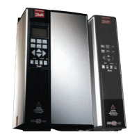
VLT® 5000 Crane
Appendix
Power monitoring ......................................................... 68
Process Bytes
.............................................................. 98
Programmable Signal Outputs
......................................... 12
Protection against Mains Interference
................................ 12
Pulse/Encoder Input
...................................................... 17
Q
Quick stop ramp-down time ............................................ 58
Quick-stop
.................................................................. 82
R
Ramp torque ............................................................... 74
Ramp-down time 1
....................................................... 58
Ramp-up time 1
........................................................... 58
Rated motor
................................................................ 55
Read parameter description elements
...............................105
References
.................................................................... 7
Relay 01, OFF delay
...................................................... 65
Relay 01, ON delay
....................................................... 65
Relay 01, output
........................................................... 65
Relay 04, output
........................................................... 65
Relay Outputs
.............................................................. 18
Reliable Galvanic Isolation
............................................... 13
Reset kWh Counter
....................................................... 71
Reset function
.............................................................. 69
Reset Run Hours
.......................................................... 71
Reversing
.................................................................... 83
RFI switch
................................................................... 33
Rotor Inertia
................................................................. 57
Rotor Leakage Reactance
.............................................. 56
Rotor Resistance
.......................................................... 56
RS 232 Serial Communication
......................................... 17
RS 485
....................................................................... 80
RS 485 Serial Communication
......................................... 17
S
Safety Earthing............................................................. 35
Safety Regulations
.......................................................... 4
Selection of Brake Resistor
............................................116
Serial Communication
.................................................... 95
Signal output 26
........................................................... 67
Signal output 46
........................................................... 66
Speed PI lowpass filter time
............................................ 69
Start
.......................................................................... 82
Start torque
................................................................. 74
Stator Leakage Reactance
.............................................. 56
Stator Resistance
......................................................... 56
Status Word in Crane Profile
...........................................100
Status word in FC profile
...............................................102
Switches 1-4
............................................................... 30
Switching on the Input
..................................................112
System Components
..................................................... 11
System Description
......................................................... 9
T
Telegram Build-up......................................................... 95
Telegram Communication
............................................... 95
Telegram Profile
............................................................ 83
Ter m inal 1 6
.................................................................. 61
Terminal 45, output
....................................................... 65
Tightening-up Torques and Screw Sizes
............................. 30
Time out
..................................................................... 64
Torque Characteristics
................................................... 16
Torque limit for generating operation
.................................. 59
Torque limit for motor mode
............................................ 59
U
Upper limit .................................................................109
V
Ventilation when Panelmounted........................................ 25
Vibration and Shock
.....................................................112
VLT 5000 Crane Protection
............................................. 19
VLT Output Data
........................................................... 16
W
Warning Against Unintended Start ...................................... 4
Warnings and Alarms, 1-6
............................................... 88
Warnings and Alarms, 19-27
........................................... 90
Warnings and Alarms, 29-49
........................................... 91
Warnings and Alarms, 7-16
............................................. 89
2
24 V DC Output............................................................ 17
MG.50.N4.02 - VLT is a registered Danfoss trademark
121
 Loading...


