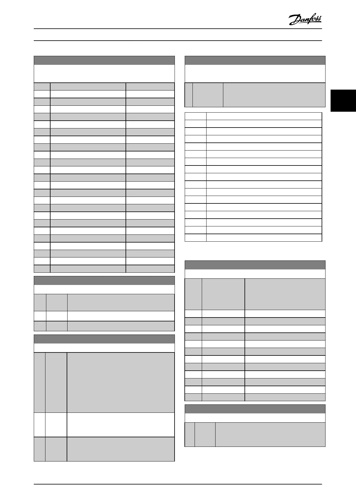
9-23 Parameters for Signals
Array [1000]
Option: Function:
[1692] Warning Word
[1693] Warning Word 2
[1694] Ext. Status Word
[1695] Ext. Status Word 2
[1696] Maintenance Word
[1830] Analog Input X42/1
[1831] Analog Input X42/3
[1832] Analog Input X42/5
[1833] Analog Out X42/7 [V]
[1834] Analog Out X42/9 [V]
[1835] Analog Out X42/11 [V]
[1836] Analog Input X48/2 [mA]
[1837] Temp. Input X48/4
[1838] Temp. Input X48/7
[1839] Temp. Input X48/10
[1850] Sensorless Readout [unit]
[1860] Digital Input 2
[2013] Minimum Reference/Feedb.
[2014] Maximum Reference/Feedb.
[2021] Setpoint 1
[2022] Setpoint 2
[2023] Setpoint 3
[2643] Terminal X42/7 Bus Control
[2653] Terminal X42/9 Bus Control
[2663] Terminal X42/11 Bus Control
9-27 Parameter Edit
Option: Function:
Parameters can be edited via PROFIBUS, the
standard RS485 interface, or the LCP.
[0] Disabled Disables editing via PROFIBUS.
[1] * Enabled Enables editing via PROFIBUS.
9-28 Process Control
Option: Function:
Process control (setting of control word, speed
reference, and process data) is possible via either
PROFIBUS or standard eldbus, but not both
simultaneously. Local control is always possible
via the LCP. Control via process control is possible
via either terminals or eldbus depending on the
settings in parameter 8-50 Coasting Select to
parameter 8-56 Preset Reference Select.
[0] Disable Disables process control via PROFIBUS, and
enables process control via standard eldbus or
PROFIBUS master class 2.
[1]
*
Enable
cyclic
master
Enables process control via PROFIBUS master class
1, and disables process control via standard
eldbus or PROFIBUS master class 2.
9-53 Probus Warning Word
Read only
Range: Function:
0* [0 - 65535 ] This parameter displays PROFIBUS communi-
cation warnings. Refer to the PROFIBUS
Operating Instructions for further information.
Bit Meaning
0 Connection with DP-master is not OK.
1 Not used.
2 FDL (eldbus data link layer) is not OK.
3 Clear data command received.
4 Actual value is not updated.
5 Baudrate search.
6 PROFIBUS ASIC is not transmitting.
7 Initialisation of PROFIBUS is not OK.
8 Frequency converter is tripped.
9 Internal CAN error.
10 Wrong conguration data from PLC.
11 Wrong ID sent by PLC.
12 Internal error occured.
13 Not congured.
14 Time-out active.
15 Warning 34 active.
Table 3.15 PROFIBUS Warning Word
9-63 Actual Baud Rate
Option: Function:
This parameter displays the actual
PROFIBUS baud rate. The PROFIBUS
master automatically sets the baud
rate.
[0] 9,6 kbit/s
[1] 19,2 kbit/s
[2] 93,75 kbit/s
[3] 187,5 kbit/s
[4] 500 kbit/s
[6] 1500 kbit/s
[7] 3000 kbit/s
[8] 6000 kbit/s
[9] 12000 kbit/s
[10] 31,25 kbit/s
[11] 45,45 kbit/s
[255] * No baudrate found
9-65 Prole Number
Range: Function:
0* [0 - 0 ] This parameter contains the prole identication.
Byte 1 contains the prole number and byte 2 the
version number of the prole.
Parameter Descriptions Programming Guide
MG11CE02 Danfoss A/S © 03/2015 All rights reserved. 99
3 3
 Loading...


