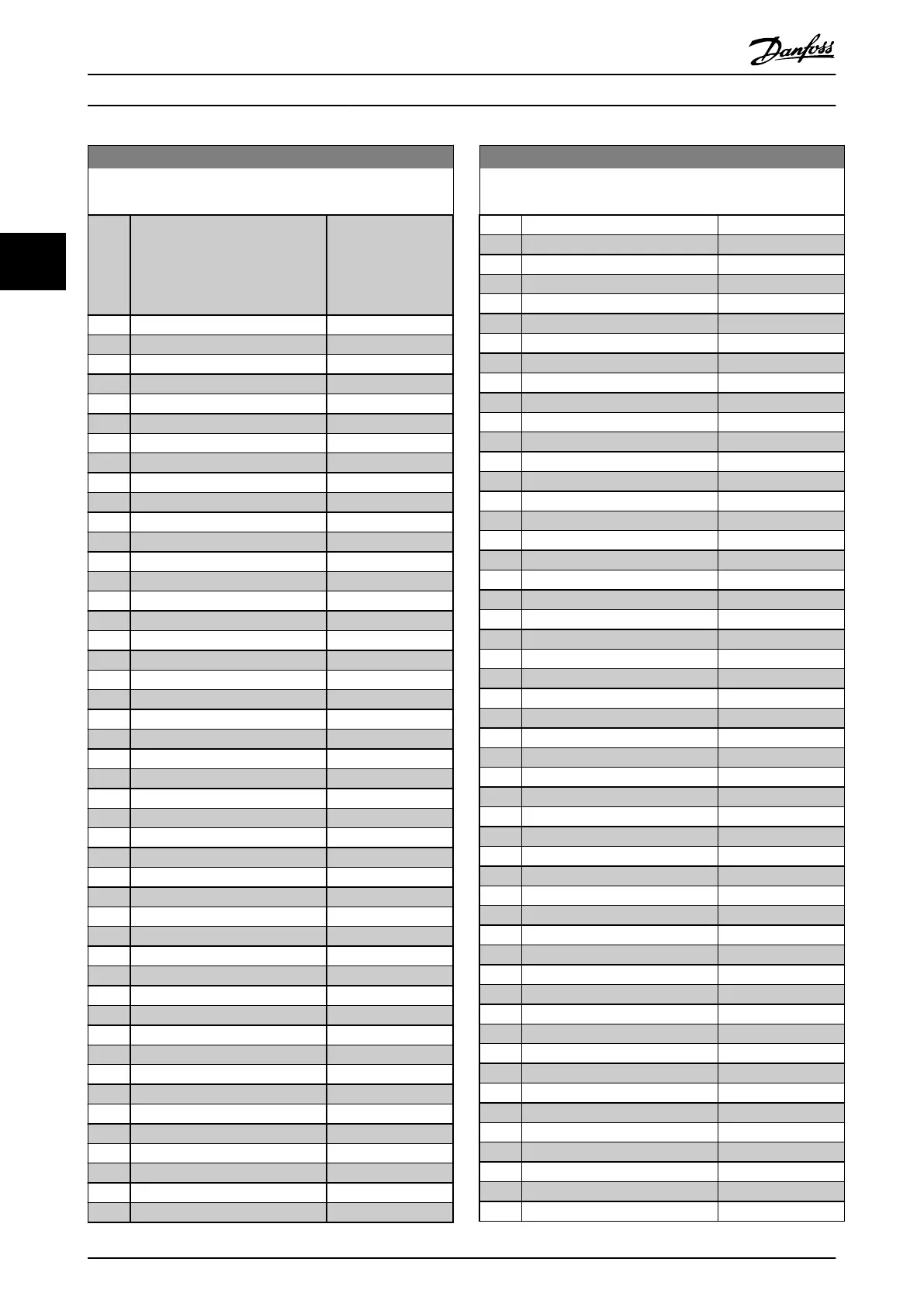
9-23 Parameters for Signals
Array [1000]
Option: Function:
parameter 9-15 PCD
Write Conguration
and
parameter 9-16 PCD
Read Conguration.
[0] * None
[302] Minimum Reference
[303] Maximum Reference
[341] Ramp 1 Ramp Up Time
[342] Ramp 1 Ramp Down Time
[351] Ramp 2 Ramp Up Time
[352] Ramp 2 Ramp Down Time
[380] Jog Ramp Time
[381] Quick Stop Ramp Time
[411] Motor Speed Low Limit [RPM]
[412] Motor Speed Low Limit [Hz]
[413] Motor Speed High Limit [RPM]
[414] Motor Speed High Limit [Hz]
[416] Torque Limit Motor Mode
[417] Torque Limit Generator Mode
[553] Term. 29 High Ref./Feedb. Value
[558] Term. 33 High Ref./Feedb. Value
[590] Digital & Relay Bus Control
[593] Pulse Out #27 Bus Control
[595] Pulse Out #29 Bus Control
[597] Pulse Out #X30/6 Bus Control
[615] Terminal 53 High Ref./Feedb. Value
[625] Terminal 54 High Ref./Feedb. Value
[653] Terminal 42 Output Bus Control
[663] Terminal X30/8 Output Bus Control
[673] Terminal X45/1 Bus Control
[683] Terminal X45/3 Bus Control
[890] Bus Jog 1 Speed
[891] Bus Jog 2 Speed
[894] Bus Feedback 1
[895] Bus Feedback 2
[896] Bus Feedback 3
[1397] Alert Alarm Word
[1398] Alert Warning Word
[1399] Alert Status Word
[1500] Operating hours
[1501] Running Hours
[1502] kWh Counter
[1600] Control Word
[1601] Reference [Unit]
[1602] Reference [%]
[1603] Status Word
[1605] Main Actual Value [%]
[1609] Custom Readout
[1610] Power [kW]
[1611] Power [hp]
9-23 Parameters for Signals
Array [1000]
Option: Function:
[1612] Motor Voltage
[1613] Frequency
[1614] Motor current
[1615] Frequency [%]
[1616] Torque [Nm]
[1617] Speed [RPM]
[1618] Motor Thermal
[1622] Torque [%]
[1623] Motor Shaft Power [kW]
[1624] Calibrated Stator Resistance
[1626] Power Filtered [kW]
[1627] Power Filtered [hp]
[1630] DC Link Voltage
[1632] Brake Energy /s
[1633] Brake Energy Average
[1634] Heatsink Temp.
[1635] Inverter Thermal
[1638] SL Controller State
[1639] Control Card Temp.
[1650] External Reference
[1652] Feedback[Unit]
[1653] Digi Pot Reference
[1654] Feedback 1 [Unit]
[1655] Feedback 2 [Unit]
[1656] Feedback 3 [Unit]
[1660] Digital Input
[1661] Terminal 53 Switch Setting
[1662] Analog Input 53
[1663] Terminal 54 Switch Setting
[1664] Analog Input 54
[1665] Analog Output 42 [mA]
[1666] Digital Output [bin]
[1667] Pulse Input #29 [Hz]
[1668] Pulse Input #33 [Hz]
[1669] Pulse Output #27 [Hz]
[1670] Pulse Output #29 [Hz]
[1671] Relay Output [bin]
[1672] Counter A
[1673] Counter B
[1675] Analog In X30/11
[1676] Analog In X30/12
[1677] Analog Out X30/8 [mA]
[1678] Analog Out X45/1 [mA]
[1679] Analog Out X45/3 [mA]
[1680] Fieldbus CTW 1
[1682] Fieldbus REF 1
[1684] Comm. Option STW
[1685] FC Port CTW 1
[1686] FC Port REF 1
[1690] Alarm Word
[1691] Alarm Word 2
Parameter Descriptions
VLT
®
HVAC Drive FC 102
98 Danfoss A/S © 03/2015 All rights reserved. MG11CE02
33
 Loading...


