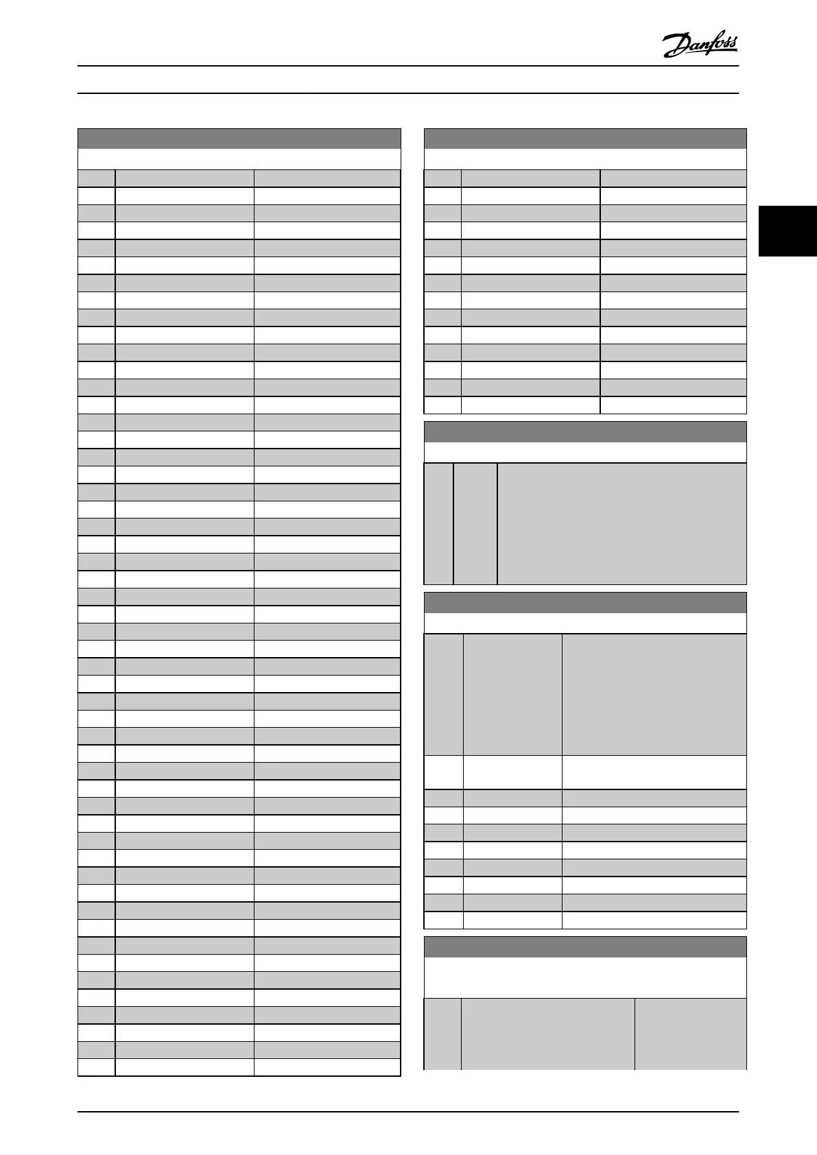
9-16 PCD Read Conguration
Option: Function:
[1611] Power [hp]
[1612] Motor Voltage
[1613] Frequency
[1614] Motor current
[1615] Frequency [%]
[1616] Torque [Nm]
[1617] Speed [RPM]
[1618] Motor Thermal
[1622] Torque [%]
[1623] Motor Shaft Power [kW]
[1624] Calibrated Stator Resistance
[1626] Power Filtered [kW]
[1627] Power Filtered [hp]
[1630] DC Link Voltage
[1632] Brake Energy /s
[1633] Brake Energy Average
[1634] Heatsink Temp.
[1635] Inverter Thermal
[1638] SL Controller State
[1639] Control Card Temp.
[1650] External Reference
[1652] Feedback[Unit]
[1653] Digi Pot Reference
[1654] Feedback 1 [Unit]
[1655] Feedback 2 [Unit]
[1656] Feedback 3 [Unit]
[1660] Digital Input
[1661] Terminal 53 Switch Setting
[1662] Analog Input 53
[1663] Terminal 54 Switch Setting
[1664] Analog Input 54
[1665] Analog Output 42 [mA]
[1666] Digital Output [bin]
[1667] Pulse Input #29 [Hz]
[1668] Pulse Input #33 [Hz]
[1669] Pulse Output #27 [Hz]
[1670] Pulse Output #29 [Hz]
[1671] Relay Output [bin]
[1672] Counter A
[1673] Counter B
[1675] Analog In X30/11
[1676] Analog In X30/12
[1677] Analog Out X30/8 [mA]
[1678] Analog Out X45/1 [mA]
[1679] Analog Out X45/3 [mA]
[1684] Comm. Option STW
[1685] FC Port CTW 1
[1690] Alarm Word
[1691] Alarm Word 2
[1692] Warning Word
[1693] Warning Word 2
[1694] Ext. Status Word
9-16 PCD Read Conguration
Option: Function:
[1695] Ext. Status Word 2
[1696] Maintenance Word
[1830] Analog Input X42/1
[1831] Analog Input X42/3
[1832] Analog Input X42/5
[1833] Analog Out X42/7 [V]
[1834] Analog Out X42/9 [V]
[1835] Analog Out X42/11 [V]
[1836] Analog Input X48/2 [mA]
[1837] Temp. Input X48/4
[1838] Temp. Input X48/7
[1839] Temp. Input X48/10
[1850] Sensorless Readout [unit]
[1860] Digital Input 2
9-18 Node Address
Range: Function:
126* [ 0 -
126 ]
Enter the station address in this parameter or
alternatively in the hardware switch. In order to
adjust the station address in parameter 9-18 Node
Address, the hardware switch must be set to 126
or 127 (that is, all switches set to ‘on’). Otherwise
this parameter displays the actual setting of the
switch.
9-22 Telegram Selection
Option: Function:
Select a standard PROFIBUS telegram
conguration for the frequency
converter, as an alternative to using
the freely congurable telegrams in
parameter 9-15 PCD Write Congu-
ration
and parameter 9-16 PCD Read
Conguration.
[1] Standard telegram
1
[101] PPO 1
[102] PPO 2
[103] PPO 3
[104] PPO 4
[105] PPO 5
[106] PPO 6
[107] PPO 7
[108] * PPO 8
9-23 Parameters for Signals
Array [1000]
Option: Function:
This parameter
contains a list of
signals available for
selection in
Parameter Descriptions Programming Guide
MG11CE02 Danfoss A/S © 03/2015 All rights reserved. 97
3 3
 Loading...


