14-22 Operation Mode
Option: Function:
Use this parameter to specify normal operation,
to perform tests, or to initialise all parameters
except
•
Parameter 15-03 Power Up's.
•
Parameter 15-04 Over Temp's.
•
Parameter 15-05 Over Volt's.
This function is active only when the power is
cycled (power
o/power on) to the frequency
converter.
[0]
*
Normal
operation
Normal operation of the frequency converter
with the motor in the selected application.
[1] Control
card test
Tests the analog and digital inputs and outputs
and the +10 V control voltage. The test
requires a test connector with internal
connections.
Use the following procedure for the control
card test:
1.
Select [1] Control card test.
2. Disconnect the mains supply and wait
for the light in the display to go out.
3. Set switches S201 (A53) and S202
(A54)=ON/I.
4. Insert the test plug (see
Illustration 3.41).
5. Connect to mains supply.
6. Carry out various tests.
7. The results are shown in the display
and the frequency converter moves
into an
innite loop.
8.
Parameter 14-22 Operation Mode is
automatically set to [0] Normal
operation. Carry out a power cycle to
start up in normal operation after a
control card test.
If the test is OK
LCP readout: Control Card OK.
Disconnect the mains supply and remove the
test plug. The green LED on the control card
lights up.
If the test fails
LCP readout: Control Card I/O failure.
Replace the frequency converter or control
card. The red LED on the control card is turned
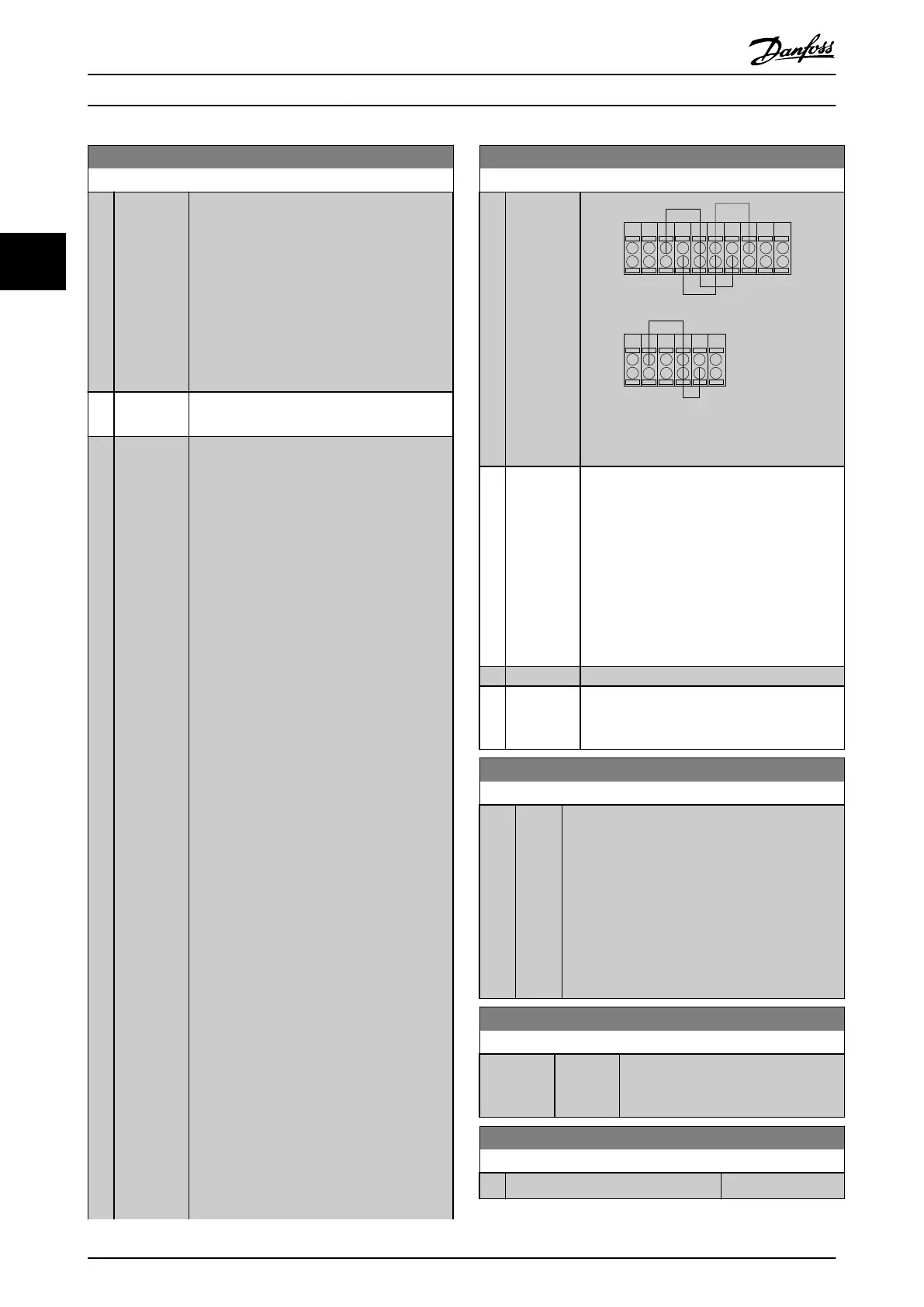
on. To test the plugs, connect/group the
following terminals as shown in Illustration 3.41:
•
(18 - 27 - 32)
•
(19 - 29 - 33)
•
(42 - 53 - 54)
14-22 Operation Mode
Option: Function:
130BA314.10
1312 18 37322719 29 33 20
5039 42 5453 55
Illustration 3.41 Wiring Control Card Test
[2] Initialisation Resets all parameter values to default settings,
except for
•
Parameter 15-03 Power Up's.
•
Parameter 15-04 Over Temp's.
•
Parameter 15-05 Over Volt's.
The frequency converter resets during the next
power-up.
Parameter 14-22 Operation Mode also reverts to
the default setting [0] Normal operation.
[3] Boot mode
[4] Initialize all
parameters
Select this option to reset all parameters
(including bus and motor parameters) to
default values.
14-25 Trip Delay at Torque Limit
Range: Function:
60 s* [0 -
60 s]
Enter the torque limit trip delay in seconds. When
the output torque reaches the torque limits
(parameter 4-16 Torque Limit Motor Mode and
parameter 4-17 Torque Limit Generator Mode), a
warning is triggered. When the torque limit
warning has been continuously present for the
period
specied in this parameter, the frequency
converter trips. Disable the trip delay by setting
the parameter to 60 s=OFF. Thermal frequency
converter monitoring remains active.
14-26 Trip Delay at Inverter Fault
Range: Function:
Size related* [0 - 35 s] When the frequency converter detects
an overvoltage in the set time, trip is
eected after the set time.
14-29 Service Code
Range: Function:
0* [-2147483647 - 2147483647 ] Service use only.
Parameter Descriptions
VLT
®
HVAC Drive FC 102
120 Danfoss A/S © 03/2015 All rights reserved. MG11CE02
33
 Loading...


