Relative value
operating variable
Counter 1: +1
Counter 0: +5
Counter 2: +0
Counter 3: +1
Counter 4: +0
Counter 5: +11
Counter 6: +1
Counter 7: +2
Counter 8: +6
Counter 9: +0
130BA281.10
80
70
50
60
30
40
10
20
%
90
100
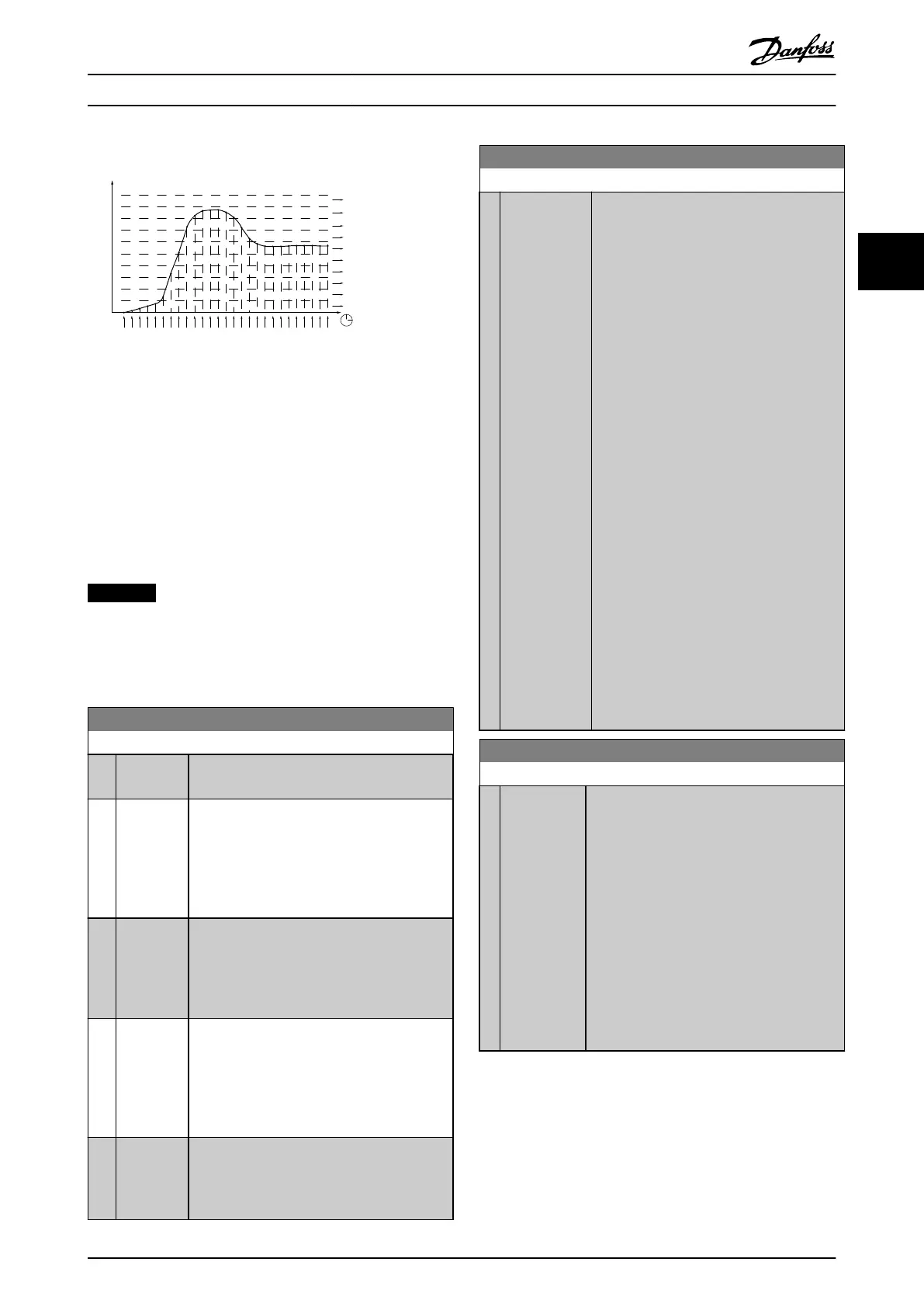
Illustration 3.64 Time and Relative Values
Once a second, the value of the operating variable
selected is registered. If a value has been registered to
equal 13%, the counter 10– <20% is updated with the
value 1. If the value stays at 13% for 10 s, 10 is added to
the counter value.
The contents of counters can be displayed as bars on the
LCP. Select Quick Menu⇒Loggings: Trending Continued Bin/
Trending Timed Bin/Trending Comparison.
NOTICE
The counters start counting whenever the frequency
converter is powered up. Power cycle shortly after a
reset zeros the counters. EEPROM data are updated once
per hour.
23-60 Trend Variable
Option: Function:
Select the desired operating variable to be
monitored for trending.
[0] Power [kW] Power yielded to the motor. Reference for the
relative value is the rated motor power
programmed in parameter 1-20 Motor Power
[kW] or parameter 1-21 Motor Power [HP]. Actual
value can be read in parameter 16-10 Power
[kW] or parameter 16-11 Power [hp].
[1] Current [A] Output current to the motor. Reference for the
relative value is the rated motor current
programmed in parameter 1-24 Motor Current.
Actual value can be read in
parameter 16-14 Motor current.
[2]
*
Frequency
[Hz]
Output frequency to the motor. Reference for
the relative value is the maximum output
frequency programmed in
parameter 4-14 Motor Speed High Limit [Hz].
Actual value can be read in
parameter 16-13 Frequency.
[3] Motor
Speed
[RPM]
Speed of the motor. Reference for relative
value is the maximum motor speed
programmed in parameter 4-13 Motor Speed
High Limit [RPM].
23-61 Continuous Bin Data
Range: Function:
0* [0 -
4294967295 ]
Array with 10 elements ([0]-[9] below
parameter number in display). Press [OK] and
step between elements with [
▲
] and [
▼
].
10 counters with the frequency of
occurrence for the operating variable
monitored, sorted according to the following
intervals:
•
Counter [0]: 0–<10%
•
Counter [1]: 10–<20%
•
Counter [2]. 20–<30%
•
Counter [3]: 30–<40%
•
Counter [4]: 40–<50%
•
Counter [5]: 50–<60%
•
Counter [6]. 60–<70%
•
Counter [7]: 70–<80%
•
Counter [8]. 80–<90%
•
Counter [9]: 90–<100% or max
The above minimum limits for the intervals
are the default limits. These can be changed
in parameter 23-65 Minimum Bin Value.
Starts to count when the frequency
converter is powered up for the
rst time. All
counters can be reset to 0 in
parameter 23-66 Reset Continuous Bin Data.
23-62 Timed Bin Data
Range: Function:
0* [0 -
4294967295 ]
Array with 10 elements ([0]-[9] below
parameter number in display). Press [OK] and
step between elements with [
▲
] and [
▼
].
10 counters with the frequency of occurrence
for the operating data monitored sorted
according to the intervals as for
parameter 23-61 Continuous Bin Data.
Starts to count at the date/time programmed
in parameter 23-63 Timed Period Start, and
stops at the time/date programmed in
parameter 23-64 Timed Period Stop. All
counters can be reset to 0 in
parameter 23-67 Reset Timed Bin Data.
Parameter Descriptions Programming Guide
MG11CE02 Danfoss A/S © 03/2015 All rights reserved. 181
3 3
 Loading...


