25-20 Staging Bandwidth
Range: Function:
10
%*
[ 1 -
par.
25-21
%]
Set the staging bandwidth (SBW) percentage to
accommodate normal system pressure uctuation.
In cascade control systems, to avoid frequent
switching of xed speed pumps, the desired
system pressure is typically kept within a
bandwidth rather than at a constant level.
The SBW is programmed as a percentage of
parameter 20-13 Minimum Reference/Feedb. and
parameter 20-14 Maximum Reference/Feedb. For
example, if the setpoint is 5 bar and the SBW is set
to 10%, a system pressure between 4.5 and 5.5 bar
is tolerated. No staging or de-staging occur within
this bandwidth.
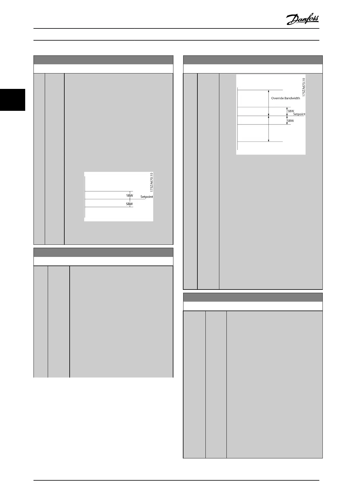
Illustration 3.69 Staging Bandwidth
25-21 Override Bandwidth
Range: Function:
100
%*
[ par.
25-20 -
100 %]
When a large and quick change in the system
demand occurs (such as a sudden water
demand), the system pressure rapidly changes
and an immediate staging or destaging of a
xed speed pump becomes necessary to match
the requirement. The override bandwidth (OBW)
is programmed to override the staging/
destaging timer (parameter 25-23 SBW Staging
Delay and parameter 25-24 SBW Destaging Delay)
for immediate response.
The OBW must always be programmed to a
higher value than the value set in
parameter 25-20 Staging Bandwidth. The OBW is
a percentage of parameter 3-02 Minimum
Reference and 3-03 Maximum Reference.
25-21 Override Bandwidth
Range: Function:
Illustration 3.71
Setting the OBW too close to the SBW could
defeat the purpose with frequent staging at
momentary pressure changes. Setting the OBW
too high might lead to unacceptably high or
low pressure in the system while the SBW
timers are running. The value can be optimised
with increased familiarity with the system. See
parameter 25-25 OBW Time.
To avoid unintended staging during the
commissioning phase and ne-tuning of the
controller, initially leave the OBW at the factory
setting of 100% (O). When the ne-tuning is
completed, the OBW should be set to the
desired value. An initial value of 10% is
suggested.
25-22 Fixed Speed Bandwidth
Range: Function:
Size
related*
[ par.
25-20 -
par.
25-21
%]
When the cascade control system is running
normally and the frequency converter issues
a trip alarm, it is important to maintain the
system head. The cascade controller does
this by continuing to stage/destage the xed
speed pump on and o. Due to the fact that
keeping the head at the setpoint would
require frequent staging and destaging
when only a xed speed pump is running, a
wider xed speed bandwidth (FSBW) is used
instead of SBW. In alarm situations, or if the
start signal on the digital input goes low, It
is possible to stop the xed speed pumps by
pressing [O] or [Hand On].
If the issued alarm is a trip-lock alarm, the
cascade controller stops the system
immediately by cutting out all the xed
speed pumps. This is basically the same as
emergency stop (coast/coast inverse
command) for the cascade controller.
Parameter Descriptions
VLT
®
HVAC Drive FC 102
192 Danfoss A/S © 03/2015 All rights reserved. MG11CE02
33
 Loading...


