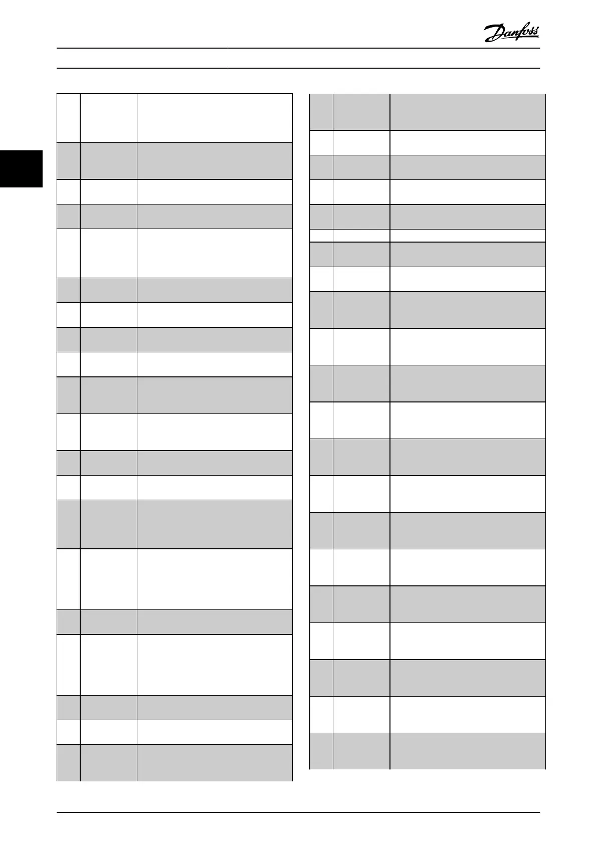
[6] Running / no
warning
The output speed is higher than the speed
set in parameter 1-81 Min Speed for
Function at Stop [RPM]. The motor is
running and there are no warnings.
[8] Run on
reference / no
warning
The motor runs at reference speed.
[9] Alarm An alarm activates the output. There are
no warnings.
[10] Alarm or
warning
An alarm or a warning activates the
output.
[11] At torque limit
The torque limit set in
parameter 4-16 Torque Limit Motor Mode or
parameter 4-13 Motor Speed High Limit
[RPM] has been exceeded.
[12] Out of current
range
The motor current is outside the range set
in parameter 4-18 Current Limit.
[13] Below current,
low
The motor current is lower than set in
parameter 4-50 Warning Current Low.
[14] Above current,
high
The motor current is higher than set in
4-51 Warning Current High.
[16] Below speed,
low
The output speed is lower than the setting
in parameter 4-52 Warning Speed Low.
[17] Above speed,
high
The output speed is higher than the
setting in parameter 4-53 Warning Speed
High.
[18] Out of
feedback
range
The feedback is outside the range set in
parameter 4-56 Warning Feedback Low and
parameter 4-57 Warning Feedback High.
[19] Below
feedback low
The feedback is below the limit set in
parameter 4-56 Warning Feedback Low.
[20] Above
feedback high
The feedback is above the limit set in
parameter 4-57 Warning Feedback High.
[21] Thermal
warning
The thermal warning turns on when the
temperature exceeds the limit in the
motor, the frequency converter, the brake
resistor, or the thermistor.
[25] Reverse The motor runs (or is ready to run)
clockwise when there is a logic 0 signal
and counterclockwise when there is a logic
1 signal. The output changes as soon as
the reversing signal is applied.
[26] Bus OK Active communication (no time-out) via
the serial communication port.
[27] Torque limit
and stop
Use this option to perform a coasting stop
and in torque limit condition. If the
frequency converter has received a stop
signal and is at the torque limit, the signal
is logic 0.
[28] Brake, no
warning
The brake is active and there are no
warnings.
[29] Brake ready,
no fault
The brake is ready for operation and there
are no faults.
[30] Brake fault
(IGBT)
The output is logic 1 when the brake IGBT
is short-circuited. Use this function to
protect the frequency converter if there is
a fault on the brake modules. Use the
output/relay to cut out the main voltage
from the frequency converter.
[35] External
Interlock
The external interlock function has been
activated via one of the digital inputs.
[40] Out of ref
range
[41] Below
reference low
[42] Above
reference high
[45] Bus Ctrl
[46] Bus Ctrl 1 if
timeout
[47] Bus Ctrl 0 if
timeout
[60] Comparator 0 See parameter group 13-1* Comparators. If
comparator 0 is evaluated as TRUE, the
output goes high. Otherwise, it is low.
[61] Comparator 1 See parameter group 13-1* Comparators. If
comparator 2 is evaluated as TRUE, the
output goes high. Otherwise, it is low.
[62] Comparator 2 See parameter group 13-1* Comparators. If
comparator 2 is evaluated as TRUE, the
output goes high. Otherwise, it is low.
[63] Comparator 3 See parameter group 13-1* Comparators. If
comparator 3 is evaluated as TRUE, the
output goes high. Otherwise, it is low.
[64] Comparator 4 See parameter group 13-1* Comparators. If
comparator 4 is evaluated as TRUE, the
output goes high. Otherwise, it is low.
[65] Comparator 5 See parameter group 13-1* Comparators. If
comparator 5 is evaluated as TRUE, the
output goes high. Otherwise, it is low.
[70] Logic Rule 0 See parameter group 13-4* Logic Rules. If
logic rule 0 is evaluated as TRUE, the
output goes high. Otherwise, it is low.
[71] Logic Rule 1 See parameter group 13-4* Logic Rules. If
logic rule 1 is evaluated as TRUE, the
output goes high. Otherwise, it is low.
[72] Logic Rule 2 See parameter group 13-4* Logic Rules. if
logic rule 2 is evaluated as TRUE, the
output goes high. Otherwise, it is low.
[73] Logic Rule 3 See parameter group 13-4* Logic Rules. If
logic rule 3 is evaluated as TRUE, the
output goes high. Otherwise, it is low.
[74] Logic Rule 4 See parameter group 13-4* Logic Rules. If
logic rule 4 is evaluated as TRUE, the
output goes high. Otherwise, it is low.
[75] Logic Rule 5 See parameter group 13-4* Logic Rules. if
logic rule 5 is evaluated as TRUE, the
output goes high. Otherwise, it is low.
[80] SL Digital
Output A
See parameter 13-52 SL Controller Action.
The input will go high whenever the smart
logic action [38] Set dig. out. A high is
Parameter Descriptions
VLT
®
HVAC Drive FC 102
74 Danfoss A/S © 03/2015 All rights reserved. MG11CE02
33
 Loading...


