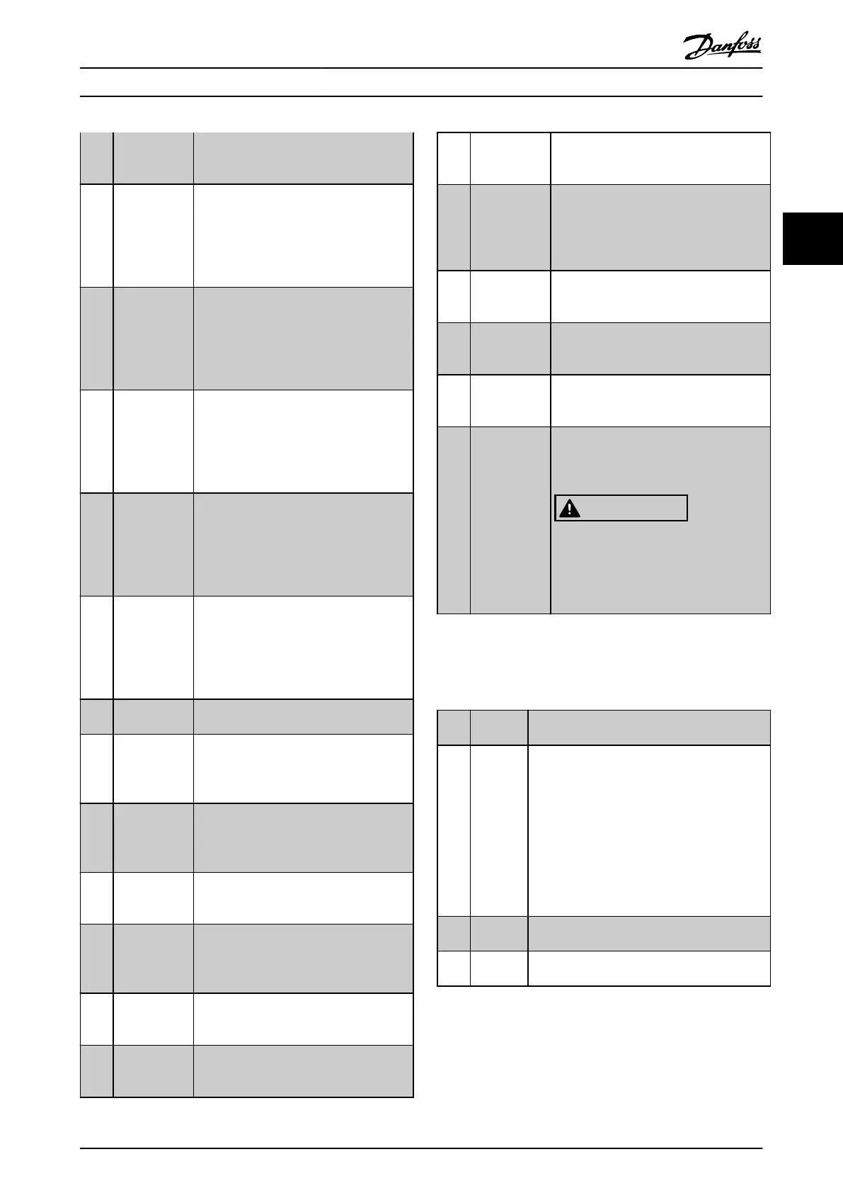
executed. The input goes low whenever
the smart logic action [32] Set dig. out. A
low is executed.
[81] SL Digital
Output B
See parameter 13-52 SL Controller Action.
The input goes high whenever the smart
logic action [39] Set dig. out. Bhigh is
executed. The input goes low whenever
the smart logic action [33] Set dig. out. B
low is executed.
[82] SL Digital
Output C
See parameter 13-52 SL Controller Action.
The input goes high whenever the smart
logic action [40] Set dig. out. C high is
executed. The input goes low whenever
the smart logic action [34] Set dig. out. C
low is executed.
[83] SL Digital
Output D
See parameter 13-52 SL Controller Action.
The input goes high whenever the smart
logic action [41] Set dig. out. D high is
executed. The input goes low whenever
the smart logic action [35] Set dig. out. D
low is executed.
[84] SL Digital
Output E
See parameter 13-52 SL Controller Action.
The input goes high whenever the smart
logic action [42] Set dig. out. E high is
executed. The input goes low whenever
the smart logic action [36] Set dig. out. E
low is executed.
[85] SL Digital
Output F
See parameter 13-52 SL Controller Action.
The input goes high whenever the smart
logic action [43] Set dig. out. F high is
executed. The input goes low whenever
the smart logic action [37] Set dig. out. F
low is executed.
[160] No alarm The output is high when no alarm is
present.
[161] Running
reverse
The output is high when the frequency
converter is running counter clockwise
(the logical product of the status bits
running AND reverse).
[165] Local
reference
active
The output is high when 3-13 Reference
Site=[2] Local or when 3-13 Reference
Site=[0] Linked to hand auto at the same
time as the LCP is in Hand mode.
[166] Remote
reference
active
The output is high when 3-13 Reference
Site = [1] Remote or [0] Linked to hand/auto
while the LCP is in Auto onmode.
[167] Start
command
active
The output is high when there is an active
start command (that is via digital input,
bus connection, [Hand on] or [Auto on]),
and no stop command is active.
[168] Drive in hand
mode
The output is high when the frequency
converter is in Hand mode (as indicated by
the LED light above [Hand On].
[169] Drive in auto
mode
The output is high when the frequency
converter is in Hand mode (as indicated by
the LED light above [Auto on].
[180] Clock Fault The clock function has been reset to
default (2000-01-01) because of a power
failure.
[181] Preventive
Maintenance
1 or more of the preventive maintenance
events programmed in
parameter 23-10 Maintenance Item has
passed the time for the specied action in
parameter 23-11 Maintenance Action.
[193] Sleep Mode The frequency converter/system has
turned into sleep mode. See parameter
group 22-4* Sleep Mode.
[194] Broken Belt A broken belt condition has been
detected. This function must be enabled in
parameter 22-60 Broken Belt Function.
[196] Fire Mode The frequency converter is operating in
Fire mode. See parameter group 24-0* Fire
Mode.
[198] Drive Bypass To be used as signal for activating an
external electromechanical bypass,
switching the motor direct on line. See
24-1* Drive Bypass.
CAUTION
If enabling the drive bypass
function, the frequency converter is
no longer safety certied (for using
the Safe Torque O in versions
where included).
The below setting options are all related to the cascade
controller.
Wiring diagrams and settings for parameter, see parameter
group 25-** Cascade Pack Controller for more details.
[200]
Full
Capacity
All pumps running and at full speed.
[201] Pump1
Running
1 or more of the pumps controlled by the
cascade controller are running. The function
also depends on parameter 25-06 Number of
Pumps. If set to [0] No, Pump 1 refers to the
pump controlled by relay RELAY1 etc. If set to
[1] Yes, Pump 1 refers to the pump controlled
by the frequency converter only (without any
of the built-in relays involved), and Pump 2 to
the pump controlled by the relay RELAY1. See
Table 3.12.
[202] Pump2
Running
See [201] Pump1 Running
[203] Pump3
Running
See [201] Pump1 Running
Parameter Descriptions Programming Guide
MG11CE02 Danfoss A/S © 03/2015 All rights reserved. 75
3 3
 Loading...


