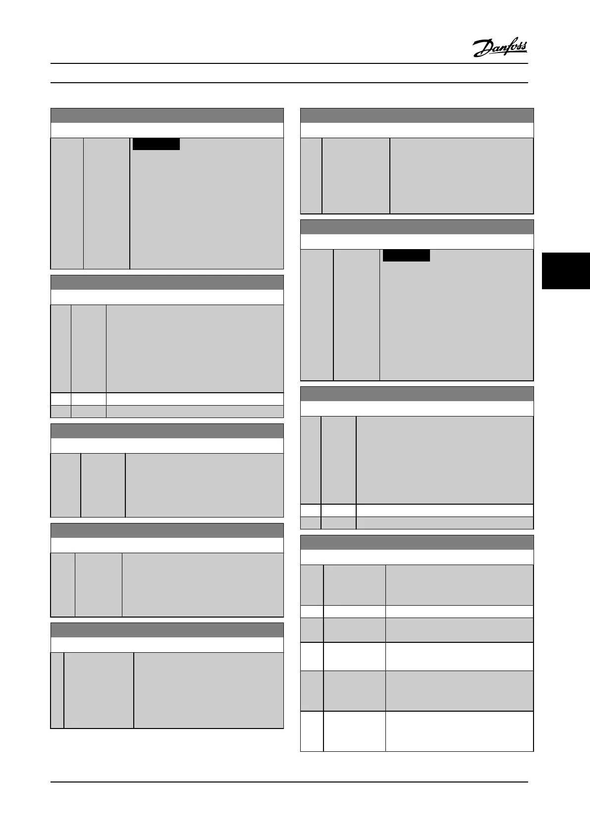
6-16 Terminal 53 Filter Time Constant
Range: Function:
0.001 s* [0.001 -
10 s]
NOTICE!
This parameter cannot be adjusted
while the motor is running.
Enter the time constant. This is a rst-order
digital low pass lter time constant for
suppressing electrical noise in terminal 53.
A high time constant value improves
dampening but also increases the time
delay through the lter.
6-17 Terminal 53 Live Zero
Option: Function:
This parameter makes it possible to disable the
Live Zero monitoring. For example, this is to be
used if the analog outputs are used as part of a
de-central I/O system (e.g., when not used as part
of any adjustable frequency drive related control
functions, but for feeding a building management
system with data).
[0] Disabled
[1] * Enabled
6-20 Terminal 54 Low Voltage
Range: Function:
0.07 V* [ 0 - par.
6-21 V]
Enter the low voltage value. This analog
input scaling value should correspond to
the low reference/feedback value, set in
parameter 6-24 Terminal 54 Low Ref./Feedb.
Value.
6-21 Terminal 54 High Voltage
Range: Function:
10 V* [ par. 6-20
- 10 V]
Enter the high voltage value. This analog
input scaling value should correspond to the
high reference/feedback value set in
parameter 6-25 Terminal 54 High Ref./Feedb.
Value.
6-24 Terminal 54 Low Ref./Feedb. Value
Range: Function:
0* [-999999.999 -
999999.999 ]
Enter the analog input scaling value that
corresponds to the low voltage/low
current value set in
parameter 6-20 Terminal 54 Low Voltage
and parameter 6-22 Terminal 54 Low
Current.
6-25 Terminal 54 High Ref./Feedb. Value
Range: Function:
100* [-999999.999 -
999999.999 ]
Enter the analog input scaling value
that corresponds to the high voltage/
high current value set in
parameter 6-21 Terminal 54 High Voltage
and parameter 6-23 Terminal 54 High
Current.
6-26 Terminal 54 Filter Time Constant
Range: Function:
0.001 s* [0.001 -
10 s]
NOTICE!
This parameter cannot be adjusted
while the motor is running.
Enter the time constant. This is a rst-order
digital low pass lter time constant for
suppressing electrical noise in terminal 54.
A high time constant value improves
dampening but also increases the time
delay through the lter.
6-27 Terminal 54 Live Zero
Option: Function:
This parameter makes it possible to disable the
Live Zero monitoring. For example, this to be
used if the analog outputs are used as part of a
de-central I/O system (e.g., when used not as part
of any adjustable frequency drive related control
functions, but for feeding a building management
system with data).
[0] Disabled
[1] * Enabled
6-50 Terminal 42 Output
Option: Function:
Select the function of Terminal 42 as an
analog current output. A motor current
of 20 mA corresponds to I
max
.
[0] No operation
[100] Output freq.
0-100
0–100 Hz, (0–20 mA)
[101] Reference Min-
Max
Minimum reference - Maximum
reference, (0–20 mA)
[102] Feedback
+-200%
-200% to +200% of
parameter 20-14 Maximum Reference/
Feedb., (0–20 mA)
[103] Motor cur. 0-
Imax
0 - Inverter Max. Current
(parameter 16-37 Inv. Max. Current), (0–20
mA)
How to Program Instruction Manual
MG11F522 Danfoss A/S © 08/2014 All rights reserved. 97
6 6
 Loading...


