6-01 Live Zero Timeout Function
Option: Function:
Select the time-out function. The function set in
parameter 6-01 Live Zero Timeout Function is
activated if the input signal on terminal 53 or
54 is below 50% of the value in
parameter 6-10 Terminal 53 Low Voltage,
6-12 Terminal 53 Low Current,
parameter 6-20 Terminal 54 Low Voltage or
6-22 Terminal 54 Low Current for a time period
defined in parameter 6-00 Live Zero Timeout
Time. If several time-outs occur simultaneously,
the frequency converter prioritises the time-out
functions as follows
1.
Parameter 6-01 Live Zero Timeout
Function
2.
8-04 Control Timeout Function
The output frequency of the frequency
converter can be:
•
[1] frozen at the present value
•
[2] overruled to stop
•
[3] overruled to jog speed
•
[4] overruled to max. speed
•
[5] overruled to stop with subsequent
trip
[0]
Off
[1] Freeze
output
[2] Stop
[3] Jogging
[4] Max. speed
[5] Stop and
trip
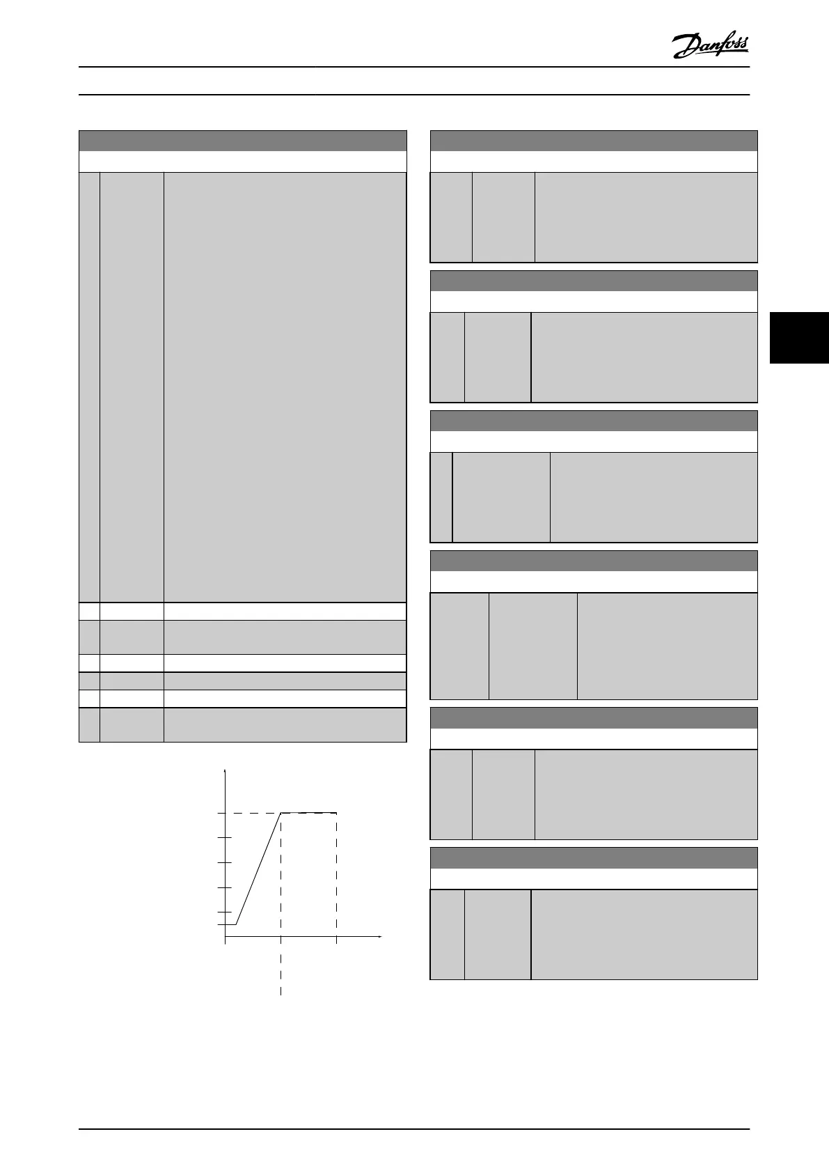
Ref./Feedback
[RPM]
Analog input
High Ref./
Feedb. Value'
Low Ref./
Feedb. Value'
'Low Voltage'or
'Low Current'
'High Voltage'or
'High Current'
130BA038.13
1 V 5 V 10 V
300
600
900
1200
1500
[V]
150
Par 6-xx
Par 6-xx
Par 6-xx
Par 6-xx
Illustration 5.18
6-10 Terminal 53 Low Voltage
Range: Function:
0.07 V* [ 0 - par.
6-11 V]
Enter the low voltage value. This analog
input scaling value should correspond to
the low reference/feedback value set in
parameter 6-14 Terminal 53 Low Ref./Feedb.
Value.
6-11 Terminal 53 High Voltage
Range: Function:
10 V* [ par. 6-10
- 10 V]
Enter the high voltage value. This analog
input scaling value should correspond to the
high reference/feedback value set in
parameter 6-15 Terminal 53 High Ref./Feedb.
Value.
6-14 Terminal 53 Low Ref./Feedb. Value
Range: Function:
0 * [-999999.999 -
999999.999 ]
Enter the analog input scaling value that
corresponds to the low voltage/low
current set in parameter 6-10 Terminal 53
Low Voltage and 6-12 Terminal 53 Low
Current.
6-15 Terminal 53 High Ref./Feedb. Value
Range: Function:
Size
related*
[-999999.999 -
999999.999 ]
Enter the analog input scaling
value that corresponds to the high
voltage/high current value set in
parameter 6-11 Terminal 53 High
Voltage and 6-13 Terminal 53 High
Current.
6-20 Terminal 54 Low Voltage
Range: Function:
0.07 V* [ 0 - par.
6-21 V]
Enter the low voltage value. This analog
input scaling value should correspond to
the low reference/feedback value, set in
parameter 6-24 Terminal 54 Low Ref./Feedb.
Value.
6-21 Terminal 54 High Voltage
Range: Function:
10 V* [ par. 6-20
- 10 V]
Enter the high voltage value. This analog
input scaling value should correspond to the
high reference/feedback value set in
parameter 6-25 Terminal 54 High Ref./Feedb.
Value.
How to programme the freque... VLT AQUA Drive FC 202 Operation Instructions
MG20P402 - Rev. 2013-12-16 99
5 5

 Loading...


