S1 S2
S2
F1
F1
S2F1
DC ‘-’
DC ‘+’
1739.1
1203.2
1163.2
1694.1
1654.1
1098.1
130BB378.10
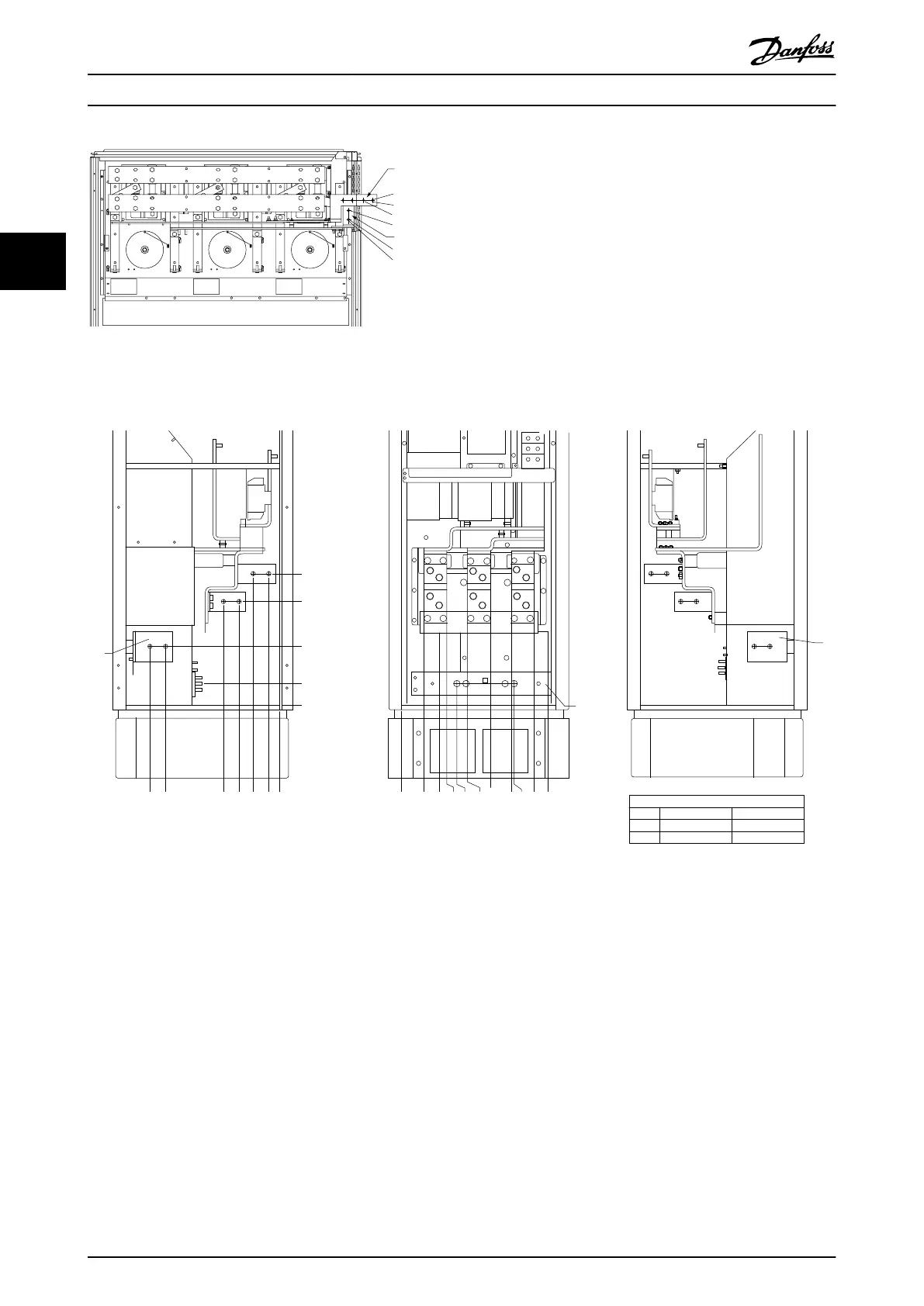
Illustration 3.27 Terminal Locations - Regen Terminals - F2 and
F4
Terminal locations - Rectifier (F1, F2, F3 and F4)
74.6 [2.9]
0.0 [0.0]
125.8 [4.95]
218.6 [8.61]
293.6 [11.56]
362.6 [14.28]
437.6 [17.23]
149.6 [5.89]
486.6 [19.16]
183.4 [7.22]
373.4 [14.70]
0.0 [0.00]
70.4 [2.77]
193.9 [7.64]
343.1 [13.51]
38.1 [1.50]
0.0 [0.00]
90.1 [3.55]
136.6 [5.38]
188.6 [7.42]
B
A
435.5 [17.15]
LOAD SHARE LOCATION
DIM F1/F2 F3/F4
A 380.5 [14.98] 29.4 [1.16]
B 432.5 [17.03] 81.4 [3.20]
6
5
4
130BA848.12
CH22 CH22
R/L1 91 S/L2 92
FASTENER TORQUE: M8 9.6 Nm (7 FT-LB)
T/L3 93
FASTENER TORQUE: M10 19 Nm (14 FT-LB)
FASTENER TORQUE: M10 19 Nm (14 FT-LB)
DC 89
FASTENER TORQUE: M10 19 Nm (14 FT-LB)
DC 89
CH22 CH22 CH22 CH22
CTI25MB CTI25MB
AUXAUXAUXAUXAUX
3
2
1
Illustration 3.28 Terminal locations - Rectifier (Left side, front and right side view). The gland plate is 42 mm below .0 level.
1) Loadshare Terminal (-)
2) Earth ground bar
3) Loadshare Terminal (+)
How to Install
VLT
®
Automation Drive FC 300 Operating Instructions
30 MG33U402 - Rev. 2013-12-16
33

 Loading...


