Terminal locations - Options Cabinet (F3 and F4)
1 2 3
4
0.0[0.00]
76.4[3.01]
128.4[5.05]
119.0[4.69]
171.0[6.73]
294.6[11.60]
344.0[13.54]
3639[14.33]
438.9[17.28]
75.3[2.96]
150.3[5.92]
154.0[6.06]
219.6[18.65]
0.0[0.00]
244.4[9.62]
244.4[1.75]
939.0[36.97]
1031.4[40.61]
0.0[0.00]
134.6[5.30]
130BA851.12
0.0[1.75]
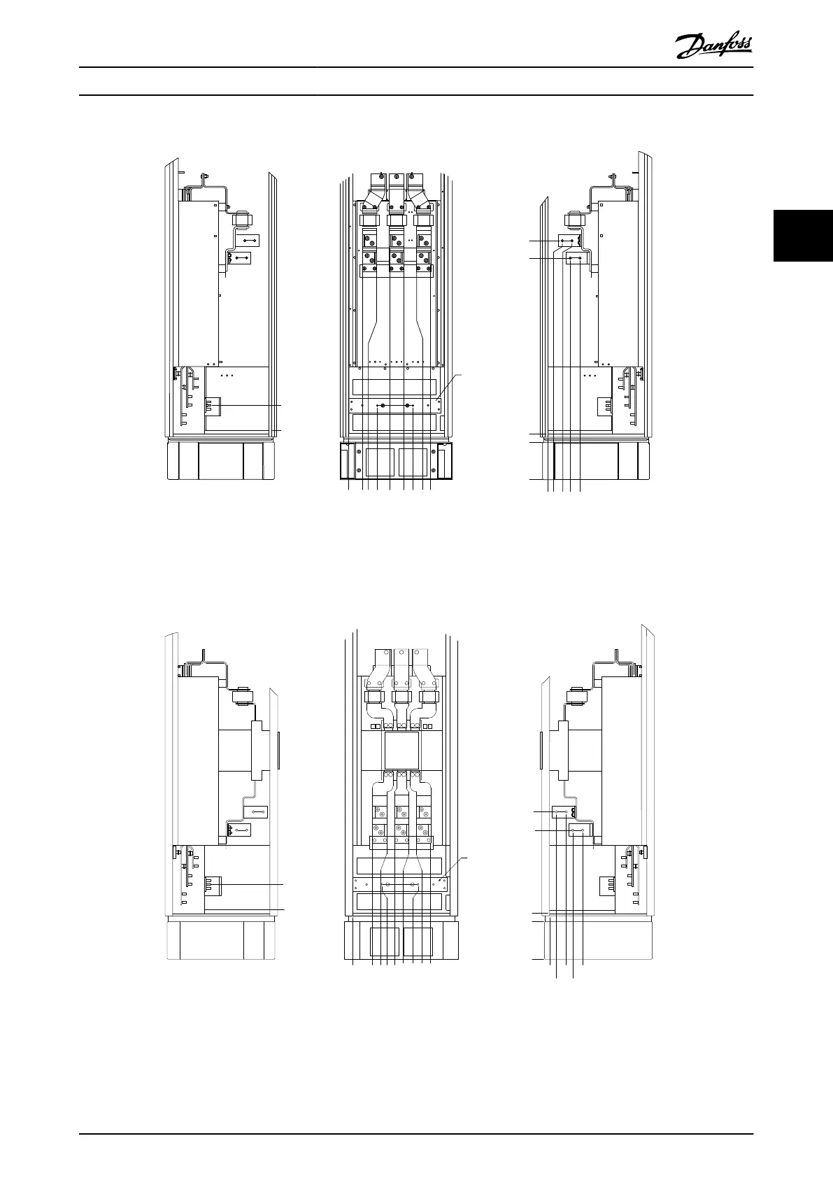
Illustration 3.29 Terminal locations - Options Cabinet (Left side, front and right side view). The gland plate is 42 mm below .0 level.
1) Earth ground bar
Terminal locations - Options Cabinet with circuit breaker/ molded case switch (F3 and F4)
0.0 [0.00]
134.6 [5.30]
104.3 [4.11]
0.0 [0.00]
179.3 [7.06]
219.6 [8.65]
294.6 [11.60]
334.8 [13.18]
409.8 [16.14]
436.9 [17.20]
0.0 [0.00]
532.9 [20.98]
0.0 [0.00]
44.4 [1.75]
244.4 [9.62]
154.0 [6.06]
344.0 [13.54]
1
2
3
4
5
130BA852.11
Illustration 3.30 Terminal locations - Options Cabinet with circuit breaker/ molded case switch (Left side, front and right side view).
The gland plate is 42 mm below .0 level.
1) Earth ground bar
How to Install
VLT
®
Automation Drive FC 300 Operating Instructions
MG33U402 - Rev. 2013-12-16 31
3 3
 Loading...


