4 Quick Set-up
4.1 Quick Set-up
4.1.1 Basic Programming Procedures
The following describes the basic procedure for running
the frequency converter.
CAUTION
When the connections are made, the compressor starts
automatically.
1. Connect the power supply to the terminals (L1,
L2 and L3) of the frequency converter as shown
in chapter 3.3.4 Mains connection for B4, C1 and
C3.
2. Connect motor cable between the frequency
converter (U, V & W) and Compressor (clockwise
on terminal), see chapter 3.3.5 Motor Compressor
Connection. (The connectors utilized in these rst
2 steps are provided in the accessory bag which
accompanies the frequency converter).
3. Press [Quick Menu] and go to quick setup. Ensure
that the correct compressor model is selected in
parameter 1-13 Compressor Selection.
4. Connect terminal 12 with terminal 18 (start
signal), terminal 12 with terminal 27 (inverse
coast signal) and terminal 12 with terminal 37*
(safe stop inverse signal).
*See chapter 3.3.10 Basic Wiring Example and
chapter 2.2.1 Terminal 37 Safe Torque
O Function.
CAUTION
If an error trips the frequency converter, it automatically
tries to restart the compressor after 30 s (unless the
error is severe and causes a trip lock). See also
parameter 14-20 Reset Mode and
parameter 14-21 Automatic Restart Time.
4.1.2 Open Loop with External Reference
1. Apply analog speed reference signal (0-10 V) on
terminal 53 using the terminal 55 as common.
See chapter 3.3.14 Basic Examples of Control
Connections.
2. Check if switch A53 is positioned to U (voltage)
instead of I (current). The switch A53 is on the
frequency converter and is visible when the LCP
is removed.
3. Ready to Run: If the frequency converter is
supplied with display: Press [Hand On] to set a
local speed reference in the display (good for
testing purposes). Press [Auto On] for running in
operation and with an external reference.
Figure 4.1 shows the screen after conguring the frequency
converter for Speed Open loop application, Hand On mode.
Figure 4.1 Speed Open Loop, Hand On Mode
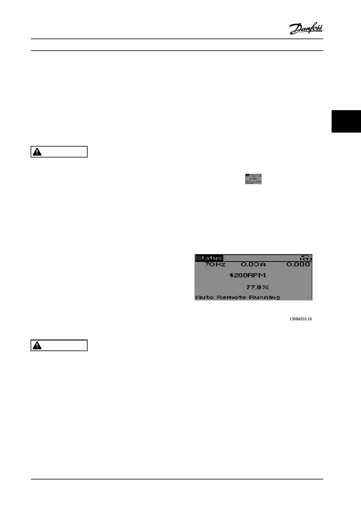
This is what the screen will look like after conguring the
frequency converter for Speed Open loop application, Auto
On mode:
Figure 4.2 Speed Open Loop, Auto On Mode
4. Done.
4.1.3 PID Closed Loop with 4-20 mA
Pressure Transmitter
1. Connect pressure transmitter to analog input on
terminal 54 according to chapter 3.3.14 Basic
Examples of Control Connections.
2. Make sure that the switch for analogue input 54
is set to “I” for current input.
3. Press [Quick Menu], go to “PID Closed Loop” and
then to “Basic PID Settings) menu.
Now change parameters to
Quick Set-up Operating Instructions
MG34M422 Danfoss A/S © Rev. 2013-07-03 All rights reserved. 37
4 4