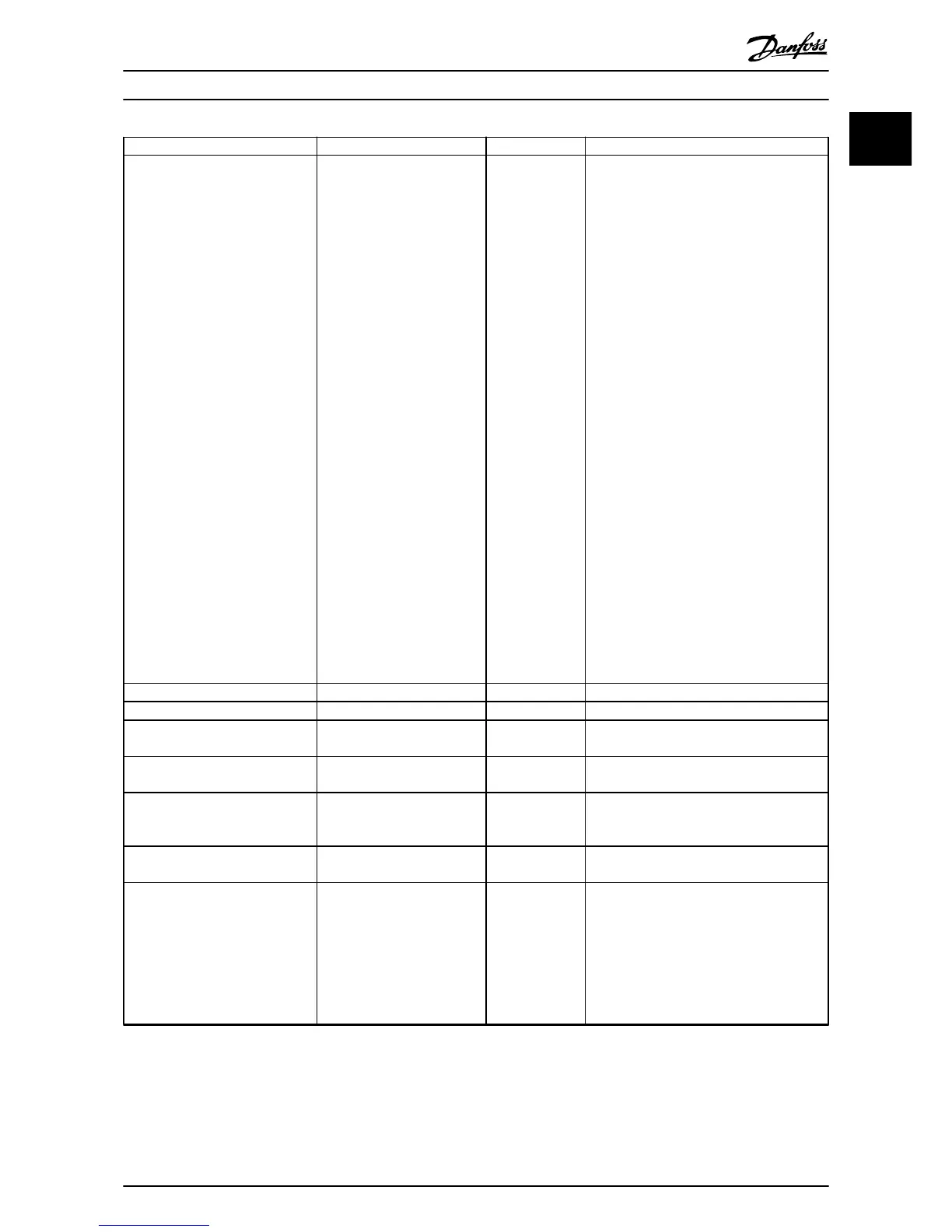
Parameter Option Default Function
5-12 Terminal 27 Digital Input
[0] No operation
[1] Reset
[2] Coast inverse
[3] Coast and reset inverse
[4] Quick stop inverse
[5] DC-brake inverse
[6] Stop inverse
[7] External Interlock
[8] Start
[9] Latched start
[10] Reversing
[11] Start reversing
[14] Jog
[16] Preset ref bit 0
[17] Preset ref bit 1
[18] Preset ref bit 2
[19] Freeze reference
[20] Speed up
[22] Speed down
[23] Set-up select bit 0
[34] Ramp bit 0
[52] Run permissive
[53] Hand start
[54] Auto start
[60] Counter A (up)
[61] Counter A (down)
[62] Reset Counter A
[63] Counter B (up)
[64] Counter B (down)
[65] Reset Counter B
[6] Stop inverse
Select the input function for terminal 27.
5-40 Function Relay [0] Function relay
See 5-40 Function Relay Alarm Select the function to control output relay 1.
5-40 Function Relay [1] Function relay
See 5-40 Function Relay Drive running Select the function to control output relay 2.
6-10 Terminal 53 Low Voltage
0-10 V 0.07 V Enter the voltage that corresponds to the low
reference value.
6-11 Terminal 53 High Voltage
0-10 V 10 V Enter the voltage that corresponds to the
high reference value.
8-01 Control Site
[0] Digital and ctrl.word
[1] Digital only
[2] Controlword only
[0] Digital and
ctrl. word
Select if digital, bus, or a combination of both
should control the frequency converter.
8-30 Protocol
[0] FC
[2] Modbus RTU
[0] FC Select the protocol for the integrated RS-485
port.
8-32 Baud Rate
[0] 2400 Baud [1]
4800 Baud
*[2] 9600 Baud
[3] 19200 Baud
4] 38400 Baud
5] 57600 Baud
[6] 76800 Baud
[7] 115200 Baud
9600 Select the baud rate for the RS-485 port.
Table 1.13 Open Loop Applications Set-up
Quick Guide
Quick Guide
MG18M102 Danfoss A/S © Rev. 09/2014 All rights reserved. 15
1
1

 Loading...


