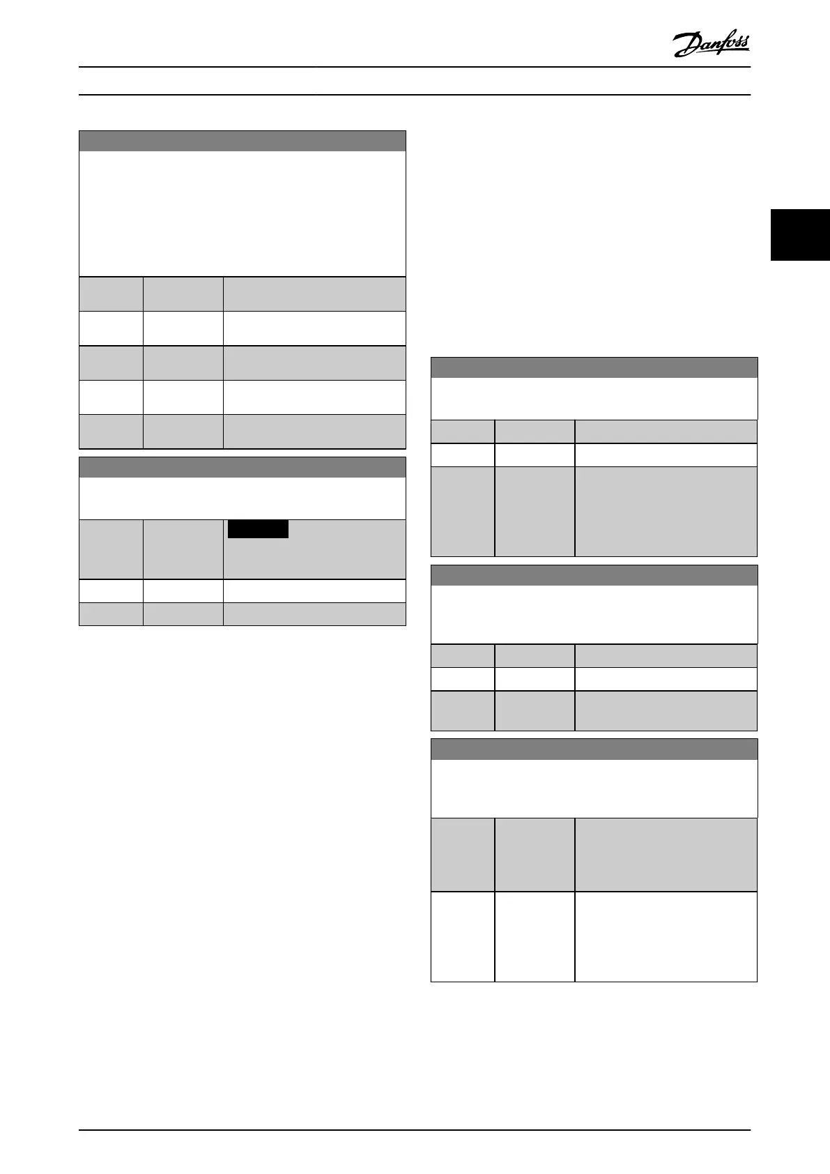
0-06 GridType
Select the grid type of the supply voltage/frequency.
IT grid is a supply mains, where there are no connections to
ground.
Delta is a supply mains where the secondary part of the
transformer is delta connected and one phase is connected to
ground.
Option: Function:
[121] 440-480V/
60Hz/Delta
[122] 440-480V/
60Hz
[130] 525-600V/
60Hz/IT-grid
[131] 525-600V/
60Hz/Delta
[132] 525-600V/
60Hz
0-07 Auto DC Braking
Protective function against overvoltage at coast.
Option: Function:
NOTICE
Can cause PWM when coasted.
[0] O This function is not active.
[1] * On This function is active.
3.1.1 0-1* Dene and Set Up Operations
A complete set of all parameters controlling the frequency
converter is called a set-up.
The frequency converter contains 2 set-ups:
•
Set-up1
•
Set-up2
Furthermore, a xed set of factory settings can be copied
into 1 or more set-ups.
Some of the advantages of having more than 1 set-up in
the frequency converter are:
•
Run compressor in 1 set-up (active set-up) while
updating parameters in another set-up (edit set-
up).
•
Connect various compressors (one at a time) to
the frequency converter. Compressor data for
various compressors can be placed in dierent
set-ups.
•
Rapidly change settings of the frequency
converter and/or compressor while the
compressor runs. For example change ramp time
or preset references via bus or digital inputs.
The active set-up can be set as multi set-up, where the
active set-up is selected via input on a digital input
terminal and/or via the bus control word.
Use parameter 0-51 Set-up Copy to copy a set-up to the
other set-ups. To avoid conicting settings of the same
parameter within 2 dierent set-ups, link the set-ups
together using parameter 0-12 Link Setups. Stop the
frequency converter before switching between set-ups
where parameters marked ‘not changeable during
operation’ have dierent values.
Parameters which are ‘not changeable during operation’
are marked FALSE in chapter 5 Parameter Lists.
0-10 Active Set-up
Select the set-up in which the frequency converter operates.
Option: Function:
[1] * Set-up 1 Set-up 1 is active.
[2] Set-up 2 Set-up 2 is active.
[9] Multi Set-up Used for remote set-up selections
via digital inputs and the serial
communication port. This set-up
uses the settings from
parameter 0-12 Link Setups.
0-11 Programming Set-up
The number of the set-up being edited is shown in the LCP,
ashing.
Option: Function:
[1] Set-up 1 Edit set-up 1.
[2] Set-up 2 Edit set-up 2.
[9] * Active Set-up Edit parameters in the set-up
selected via digital I/Os.
0-12 Link Setups
If the set-ups are not linked, a change between them is not
possible while the compressor is running.
Option: Function:
[0] Not linked When selecting a dierent set-up
for operation, the set-up change
does not occur until the
compressor is coasted.
[20] * Linked Copies “not changeable during
operation” parameters from one
set-up to the other. It is possible to
switch set-up while the compressor
is running.
Parameters Programming Guide
MG18P202 Danfoss A/S © 06/2019 All rights reserved. 19
3 3

 Loading...


