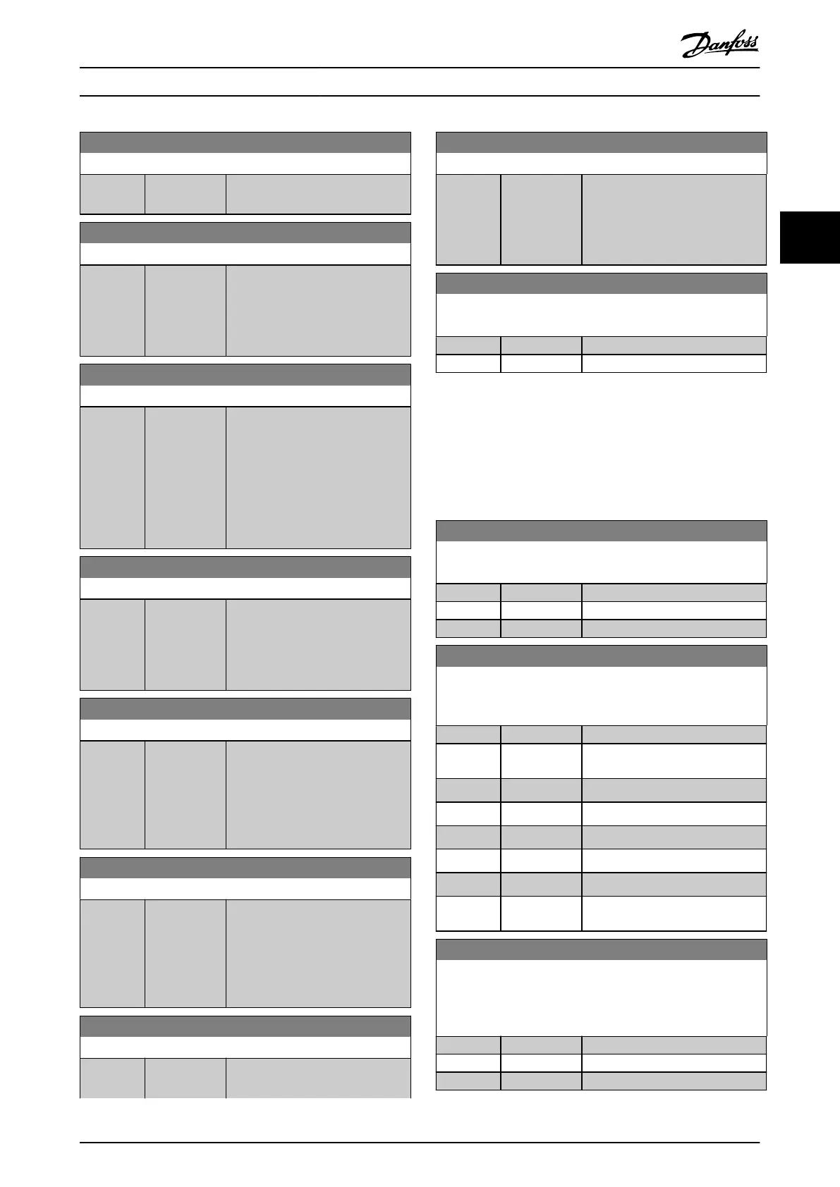
6-20 Terminal 54 Low Voltage
Range: Function:
parameter 6-01 Live Zero Timeout
Function, set the value to >1 V.
6-21 Terminal 54 High Voltage
Range: Function:
10 V* [0 - 10 V] Enter the voltage (V) that
corresponds to the high reference
value (set in
parameter 6-25 Terminal 54 High
Ref./Feedb. Value).
6-22 Terminal 54 Low Current
Range: Function:
4 mA* [0 - 20 mA] Enter the low current value. This
reference signal corresponds to the
low reference/ feedback value set in
parameter 6-24 Terminal 54 Low Ref./
Feedb. Value. To activate the live
zero timeout function in
parameter 6-01 Live Zero Timeout
Function, set the value to >2 mA.
6-23 Terminal 54 High Current
Range: Function:
20 mA* [0 - 20 mA] Enter the high current value
corresponding to the high
reference/feedback value set in
parameter 6-25 Terminal 54 High
Ref./Feedb. Value.
6-24 Terminal 54 Low Ref./Feedb. Value
Range: Function:
0* [-4999 -
4999 ]
Enter the reference or feedback
value that corresponds to the
voltage or current set in
parameter 6-21 Terminal 54 High
Voltage / parameter 6-22 Terminal 54
Low Current.
6-25 Terminal 54 High Ref./Feedb. Value
Range: Function:
Size
related*
[-4999 -
4999 ]
Enter the reference or feedback
value that corresponds to the
voltage or current set in
parameter 6-21 Terminal 54 High
Voltage / parameter 6-23 Terminal 54
High Current.
6-26 Terminal 54 Filter Time Constant
Range: Function:
0.01 s* [0.01 - 10 s] Enter the time constant, which is a
rstorder digital low-pass lter time
6-26 Terminal 54 Filter Time Constant
Range: Function:
constant for suppressing electrical
noise in terminal 54. A high time
constant value improves
dampening, but also increases the
time delay through the lter.
6-29 Terminal 54 mode
Select if terminal 54 is used for current- or voltage input.
Option: Function:
[0] * Current mode
[1] Voltage mode
3.7.4 6-7* Analog/Digital Output 45
Parameters for conguring the scaling and limits for
analog/digital output terminal 45. Analog outputs are
current outputs: 0/4–20 mA. Resolution on analog output
is 12 bit. Analog output terminals can also be set up as
digital output.
6-70 Terminal 45 Mode
Set terminal 45 to act as analog output or as digital output.
Option: Function:
[0] * 0-20 mA
[1] 4-20 mA
[2] Digital Output
6-71 Terminal 45 Analog Output
Select the function of terminal 45 as an analog current output.
See also parameter 6-70 Terminal 45 Mode.
Option: Function:
[0] * No operation
[100] Output
frequency
0–400 Hz
[101] Reference Min
Ref.
–Max
Ref.
[102] Feedback Min
FB
–Max
FB
[103] Motor Current 0–I
max
[106] Power 0–P
nom
[139] Bus Control 0–100%
[254] DC Link
Voltage
6-72 Terminal 45 Digital Output
Select the function of terminal 45 as a digital current output. See
also parameter 6-70 Terminal 45 Mode. See
parameter 5-40 Function Relay for description of the options.
Option: Function:
[0] * No operation
[1] Control Ready
[2] Drive ready
Parameters Programming Guide
MG18P202 Danfoss A/S © 06/2019 All rights reserved. 37
3 3

 Loading...


