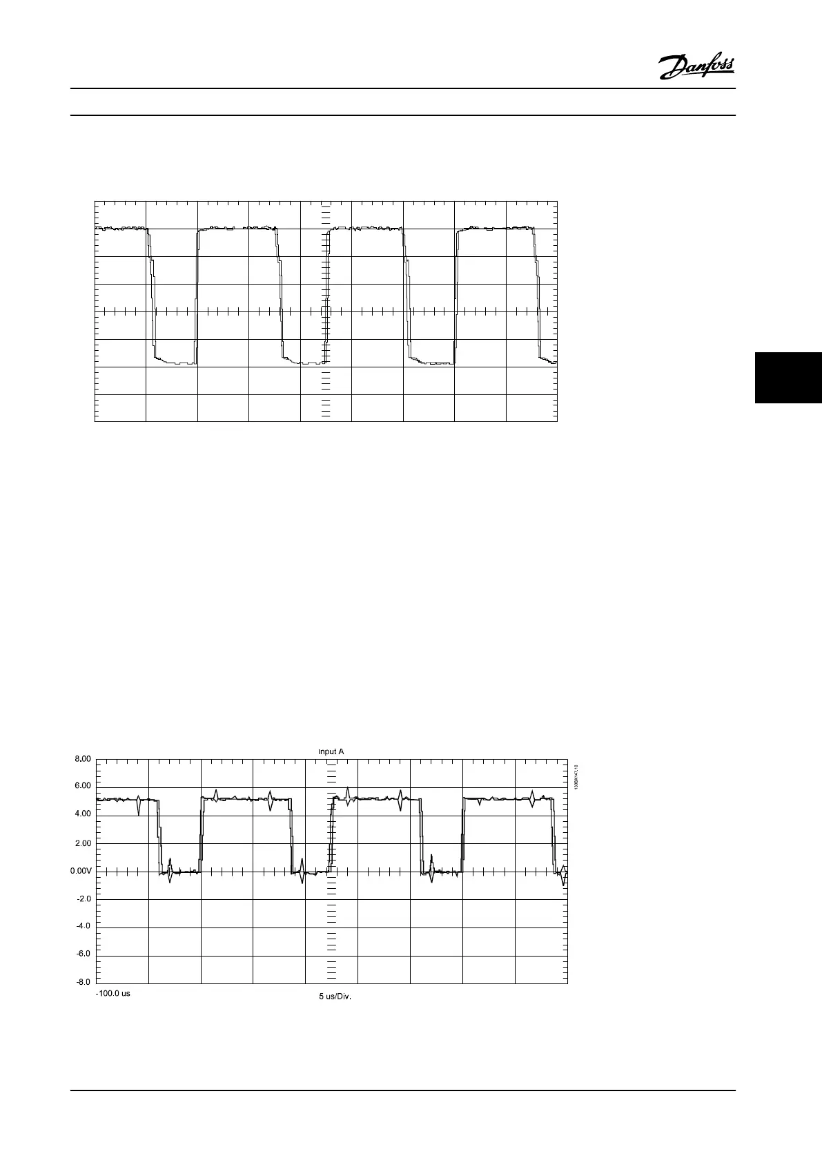
When using an oscilloscope, the readings in Figure 6.10 are correct.
20.0
15.0
10.0
5.0
0.0V
-5.0
-10.0
-15.0
-20.0
-100.0 us 5 us/Div.
Input A
130BX146.10
Figure 6.10 Gate Signal Waveform from Gate Drive Card
IGBT Gate Signal measured on the Gate Drive Card: 5 V per division vertical scale, 50 ms per division time scale. Unit
running at 30 Hz.
An incorrect reading of a gate signal indicates that the gate drive card is defective or the signal has been lost before
arriving at the gate card. The gate signals can then be checked with the signal test board to verify their presence from the
control card to the power card as follows.
5. Insert the signal test board into power card connector MK104.
6. With scope probe common connected to terminal 4 (common) of the signal board, measure six gate signals at
signal board terminals 25 through 30.
7. Place the adjustable frequency drive in run at 30 Hz.
The waveform in Figure 6.11 is the correct result.
Figure 6.11 Gate Signal Waveform from Signal Test Board
Test Procedures Service Manual
MG94A222 Danfoss A/S © Rev. 2014-02-10 All rights reserved. 85
6 6

 Loading...


