3.3.3 Earthing
The following basic issues need to be considered when
installing a frequency converter, so as to obtain electro-
magnetic compatibility (EMC).
•
Safety earthing: The frequency converter has a
high leakage current and must be earthed
appropriately for safety reasons. Apply local
safety regulations.
•
High-frequency earthing: Keep the earth wire
connections as short as possible.
Connect the different earth systems at the lowest possible
conductor impedance. The lowest possible conductor
impedance is obtained by keeping the conductor as short
as possible and by using the greatest possible surface area.
The metal cabinets of the different devices are mounted
on the cabinet rear plate using the lowest possible HF
impedance. This avoids having different HF voltages for
the individual devices and avoids the risk of radio
interference currents running in connection cables that
may be used between the devices. The radio interference
will have been reduced.
In order to obtain a low HF impedance, use the fastening
bolts of the devices as HF connection to the rear plate. It is
necessary to remove insulating paint or similar from the
fastening points.
3.3.4
Extra Protection (RCD)
ELCB relays, multiple protective earthing or earthing can
be used as extra protection, provided that local safety
regulations are complied with.
In the case of an earth fault, a DC component may
develop in the fault current.
If ELCB relays are used, local regulations must be observed.
Relays must be suitable for protection of 3-phase
equipment with a bridge rectifier and for a brief discharge
on power-up.
See also Special Conditions in the Design Guide,
MG33BXYY.
3.3.5
RFI Switch
Mains supply isolated from earth
If the frequency converter is supplied from an isolated
mains source ( IT mains, floating delta and grounded delta)
or TT/TN-S mains with grounded leg, the RFI switch is
recommended to be turned off (OFF)
1)
via 14-50 RFI Filter
on the frequency converter and 14-50 RFI Filter on the
filter. For further reference, see IEC 364-3. In case optimum
EMC performance is needed, parallel motors are connected
or the motor cable length is above 25 m, it is
recommended to set 14-50 RFI Filter to [ON].
1)
Not available for 525-600/690 V frequency converters.
In OFF, the internal RFI capacities (filter capacitors)
between the chassis and the intermediate circuit are cut
off to avoid damage to the intermediate circuit and to
reduce the earth capacity currents (according to IEC
61800-3).
Please also refer to the application note VLT on IT mains,
MN90CX02. It is important to use isolation monitors that
are capable for use together with power electronics (IEC
61557-8).
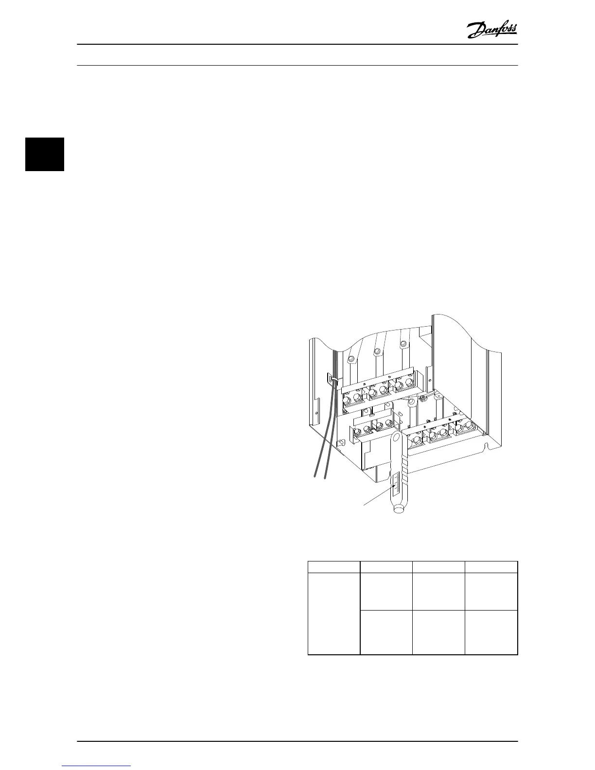
3.3.6
Torque
When tightening all electrical connections it is important
to tighten with the correct torque. Too low or too high
torque results in a poor electrical connection. Use a torque
wrench to ensure correct torque.

 Loading...


