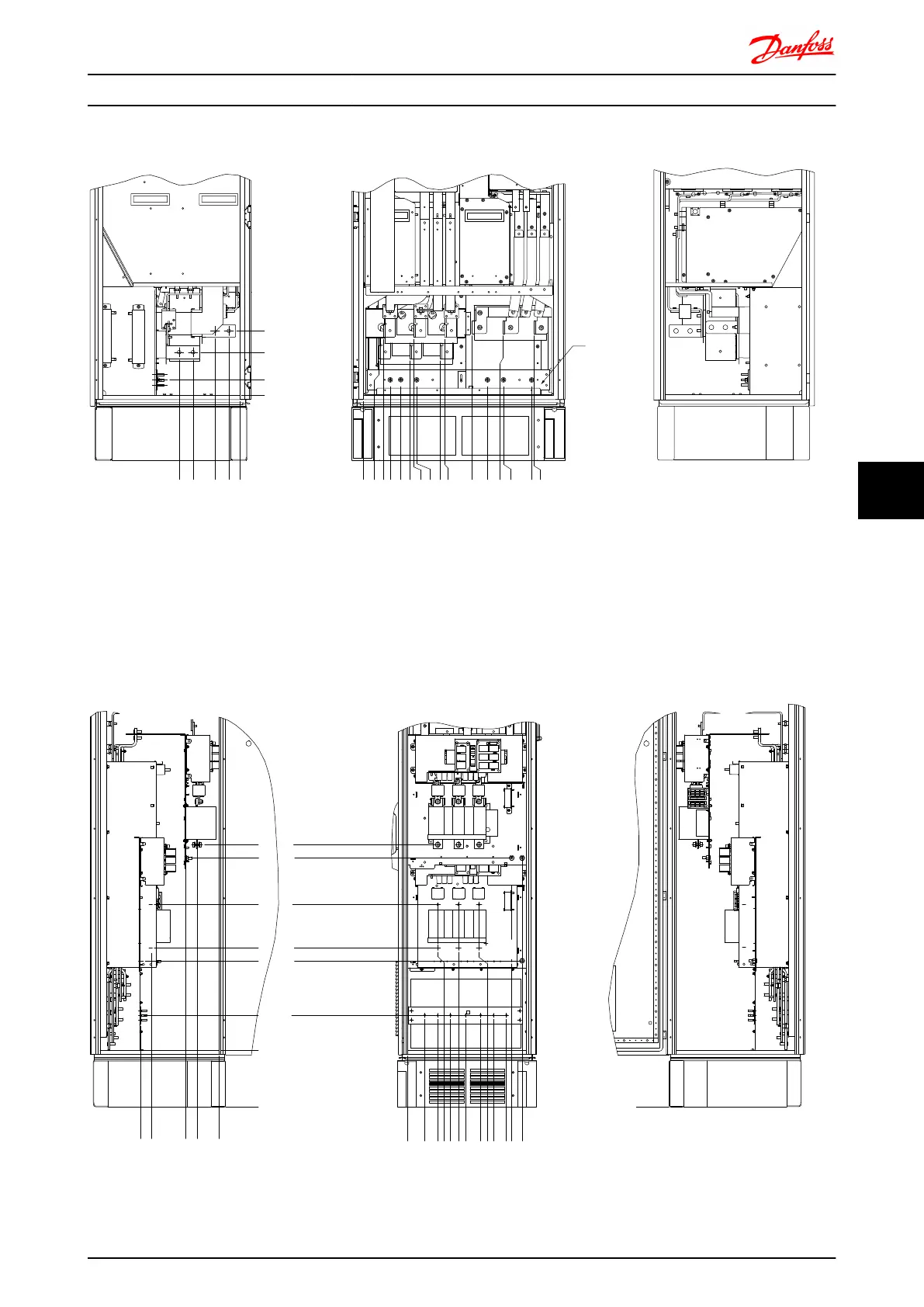
Terminal locations - Rectifier (F10, F11, F12 and F13)
1
239.6 [ 9.43 ]
0.0 [ 0.00 ]
0.0 [ 0.00 ]
160.0 [ 6.30 ]
56.6 [ 2.23 ]
39.8 [ 1.57 ]
91.8 [ 3.61 ]
174.1 [ 6.85 ]
226.1 [ 8.90 ]
130BB534.10
R2/L12
R1/L11
91-1
91
S2/L22
S1/L21
92-1
T2/L32 93-1
92
T1/L31 93
U/T1 96 V/T2 97 W/T3 98
0.0 [ 0.00 ]
57.6 [ 2.27 ]
74.0 [ 2.91 ]
100.4 [ 3.95 ]
139.4 [ 5.49 ]
172.6 [ 6.80 ]
189.0 [ 7.44 ]
199.4 [ 7.85 ]
287.6 [ 11.32 ]
304.0 [ 11.97 ]
407.3 [ 16.04 ]
464.4 [ 18.28 ]
522.3 [ 20.56 ]
524.4 [ 20.65 ]
629.7 [ 24.79 ]
637.3 [ 25.09 ]
Illustration 7.36 Terminal locations - Rectifier (Left side, front and right side view). The gland plate is 42mm below .0 level.
1) Loadshare Terminal (-)
2) Earth ground bar
3) Loadshare Terminal (+)
Terminal locations - Options Cabinet Frame Size F9
336.4
291.2
142.0
92.0
.0
.0
73.0
128.5
129.3
184.0
218.3
249.0
314.0
307.3
369.5
448.0
493.0
425.0
244.4
151.3
386.7
443.8
628.8
830.3
887.4
.0
130BB756.10
Illustration 7.37 Terminal locations - Options Cabinet (Left side, front and right side view).
Mechanical Installation - ... FC 300 Design Guide
MG.33.BD.02 - VLT
®
is a registered Danfoss trademark 149
7 7
 Loading...


