the 1950s but which has stood the test of time and is still
used today. This method is known as the Ziegler Nichols
tuning method.
The method described must not be used on applications
that could be damaged by the oscillations created by
marginally stable control settings.
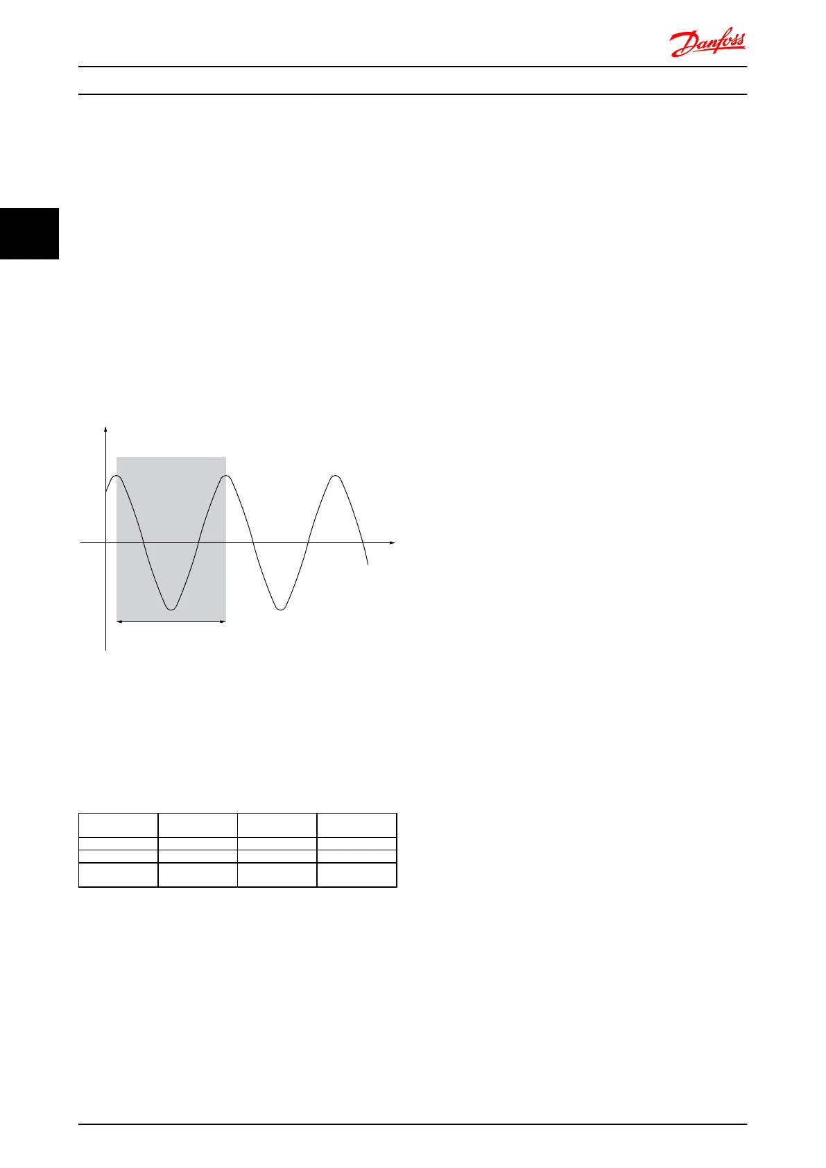
The criteria for adjusting the parameters are based on
evaluating the system at the limit of stability rather than
on taking a step response. We increase the proportional
gain until we observe continuous oscillations (as measured
on the feedback), that is, until the system becomes
marginally stable. The corresponding gain (K
u
) is called the
ultimate gain. The period of the oscillation (P
u
) (called the
ultimate period) is determined as shown in the figure.
Illustration 3.8 Marginally Stable System
P
u
should be measured when the amplitude of oscillation
is quite small. Then we “back off” from this gain again, as
shown in Table 1.
K
u
is the gain at which the oscillation is obtained.
Type of Control
Proportional
Gain
Integral Time Differentiation
Time
PI-control
0.45 * K
u
0.833 * P
u
-
PID tight control
0.6 * K
u
0.5 * P
u
0.125 * P
u
PID some
overshoot
0.33 * K
u
0.5 * P
u
0.33 * P
u
Table 3.4 Ziegler Nichols tuning for regulator, based on a stability boundary.
Experience has shown that the control setting according to
Ziegler Nichols rule provides a good closed loop response
for many systems. The process operator can do the final
tuning of the control iteratively to yield satisfactory
control.
Step-by-step Description:
Step 1: Select only Proportional Control, meaning that the
Integral time is selected to the maximum value, while the
differentiation time is selected to zero.
Step 2: Increase the value of the proportional gain until
the point of instability is reached (sustained oscillations)
and the critical value of gain, K
u
, is reached.
Step 3: Measure the period of oscillation to obtain the
critical time constant, P
u
.
Step 4: Use the table above to calculate the necessary PID
control parameters.
Introduction to FC 300 FC 300 Design Guide
36 MG.33.BD.02 - VLT
®
is a registered Danfoss trademark
3
3
 Loading...


