130BT116.1
Figure 2.13: Step 7: Use the up/down navigation keys to
navigate between the different choices. Press [OK].
Function Set-ups parameters
The Function Set-ups parameters are grouped in the following way:
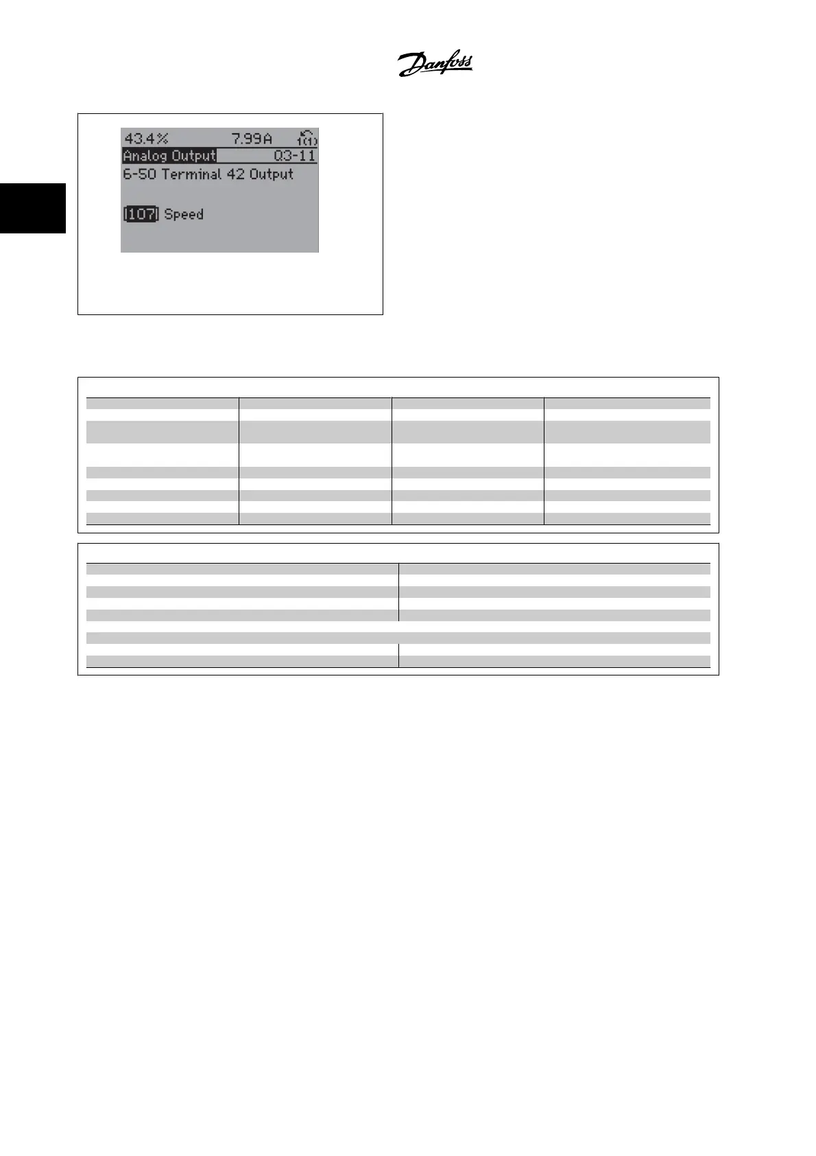
Q3-1 General Settings
Q3-10 Adv. Motor Settings Q3-11 Analog Output Q3-12 Clock Settings Q3-13 Display Settings
par.1-90
Motor Thermal Protection
par.6-50
Terminal 42 Output
par.0-70
Set Date and Time
par.0-20
Display Line 1.1 Small
par.1-93
Thermistor Source
par.6-51
Terminal 42 Output Min
Scale
par.0-71
Date Format
par. 0-21
Display Line 1.2 Small
par.1-29
Automatic Motor Adapta-
tion (AMA)
par.6-52
Terminal 42 Output Max
Scale
par.0-72
Time Format
par. 0-22
Display Line 1.3 Small
par.14-01
Switching Frequency
par.0-74
DST/Summertime
par. 0-23
Display Line 2 Large
par.4-53
Warning Speed High
par.0-76
DST/Summertime Start
par. 0-24
Display Line 3 Large
par.0-77
DST/Summertime End
par.0-37
Display Text 1
par.0-38
Display Text 2
par.0-39
Display Text 3
Q3-2 Open-loop Settings
Q3-20 Digital Reference Q3-21 Analog Reference
par.3-02
Minimum Reference
par.3-02
Minimum Reference
par.3-03
Maximum Reference
par.3-03
Maximum Reference
par.3-10
Preset Reference
par.6-10
Terminal 53 Low Voltage
par.5-13
Terminal 29 Digital Input
par.6-11
Terminal 53 High Voltage
par.5-14
Terminal 32 Digital Input
par.6-12
Terminal 53 Low Current
par.5-15
Terminal 33 Digital Input
par.6-13
Terminal 53 High Current
par.6-14
Terminal 53 Low Ref./Feedb. Value
par.6-15
Terminal 53 High Ref./Feedb. Value
2 How to Program VLT
®
HVAC Drive Programming Guide
2-14
MG.11.C6.22 - VLT
®
is a registered Danfoss trademark
2

 Loading...


