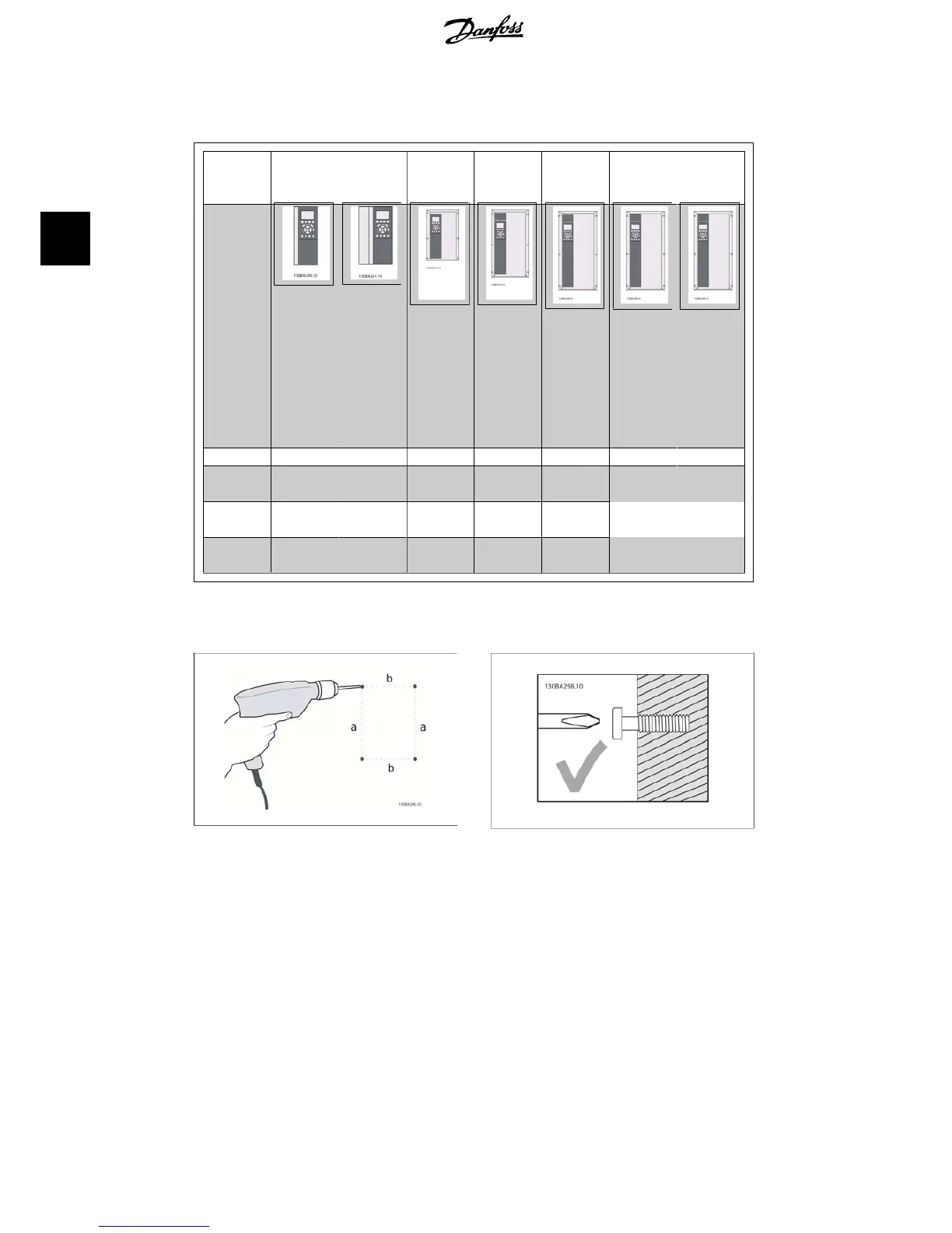
Please use the following table to follow mounting instructions
Enclo-
sure:
A2 (IP 20/
IP 21)
A3 (IP 20/
IP 21)
A5 (IP 55/
IP 66)
B1 (IP 21/
IP 55/
IP66)
B2 (IP 21/
IP 55/
IP66)
C1 (IP21/
IP 55/66)
C2 (IP21/
IP 55/66)
Unit size:
200-240 V 1.1-3.0
kW
3.7
kW
1.1-3.7
kW
5.5-11
kW
15
kW
18.5 - 30
kW
37 - 45
kW
380-480 V 1.1-4.0
kW
5.5-7.5
kW
1.1-7.5
kW
11-18.5
kW
22-30
kW
37 - 55
kW
75 - 90
kW
525-600 V 1.1-4.0
kW
5.5-7.5
kW
Table 3.2: Mounting table.
3.2.2. Mounting A2 and A3
Illustration 3.5: Drilling of holes
Step 1: Drill according to the dimensions in the
following table.
Illustration 3.6: Correct mounting of screws.
Step 2A: This way it is easy to hang the unit
on the screws.
3. Mechanical installation VLT
®
HVAC Drive Operating Instructions
16
MG.11.A4.02 - 09.10.06. VLT
®
is a registered Danfoss trademark
3