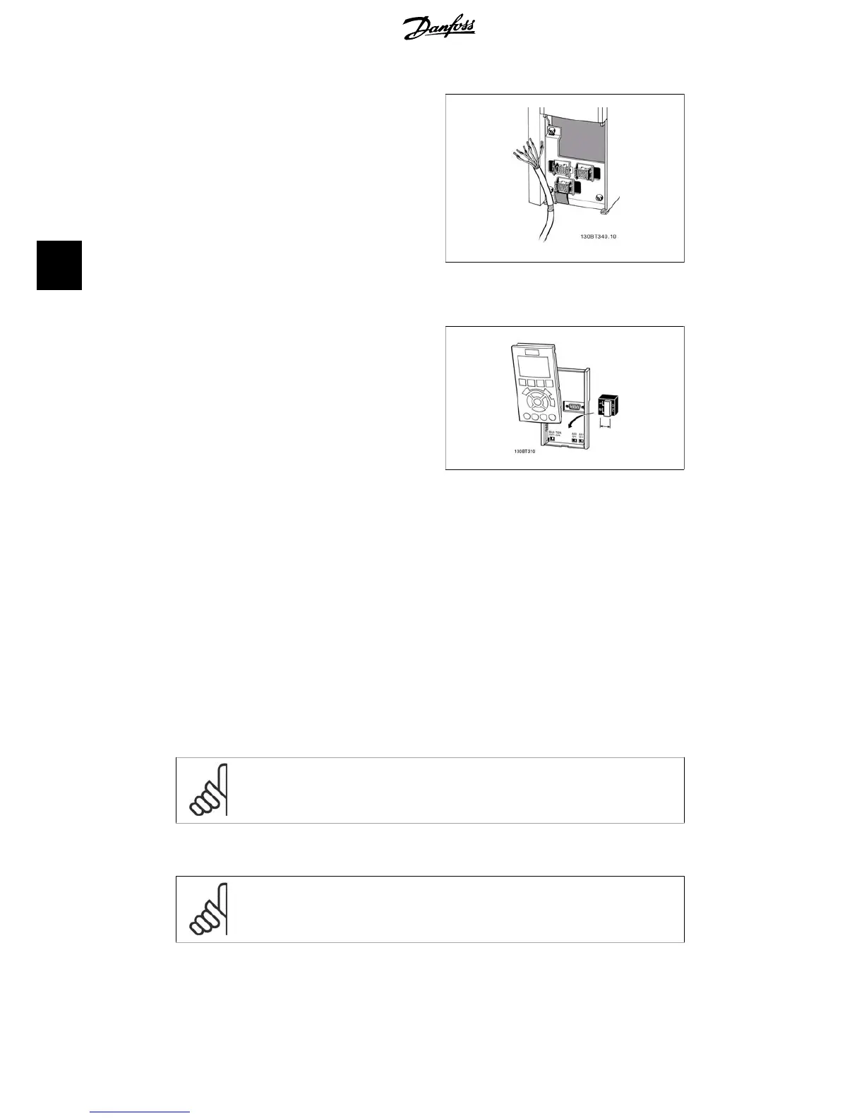
1. Use a clamp from the accessory bag
to connect screen to frequency con-
verter decoupling plate for control
cables.
See section entitled
Earthing of Screened/
Armoured Control Cables
for the correct ter-
mination of control cables.
Illustration 4.29: Control cable clamp.
4.1.20. Switches S201, S202, and S801
Switches S201 (Al53) and S202 (Al54) are
used to select a current (0-20 mA) or a voltage
(0 to 10 V) configuration of the analog input
terminals 53 and 54 respectively.
Switch S801 (BUS TER.) can be used to enable
termination on the RS-485 port (terminals 68
and 69).
Please note that the switches may be covered
by an option, if fitted.
Default setting:
S201 (A53) = OFF (voltage input)
S202 (A54) = OFF (voltage input)
S801 (Bus termination) = OFF
Illustration 4.30: Switches location.
4.2. Final optimization and test
4.2.1. Final optimization and test
To optimize motor shaft performance and optimize the frequency converter for the connected
motor and installation, please follow these steps. Ensure that frequency converterfrequency con-
verter and motor are connected, and power is applied to frequency converter.
NB!
Before power up ensure that connected equipment is ready for use.
Step 1. Locate motor name plate..
NB!
The motor is either star- (Y) or delta- connected (). This information is located on
the motor name plate data.
4. Electrical installation VLT
®
HVAC Drive Operating Instructions
38
MG.11.A4.02 - 09.10.06. VLT
®
is a registered Danfoss trademark
4