Remove mains power from the frequency converter before changing motor wires.
4.1.19. Electrical Installation and Control Cables
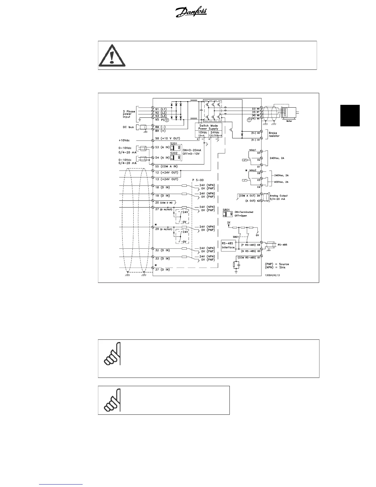
Illustration 4.28: Diagram showing all electrical terminals. (Terminal 37 present for units with Safe Stop
function only.)
Very long control cables and analog signals may, in rare cases and depending on installation, result
in 50/60 Hz earth loops due to noise from mains supply cables.
If this occurs, break the screen or insert a 100 nF capacitor between screen and chassis.
NB!
Connect the common of digital and analog inputs and outputs to separate frequency
converter common terminals 20, 39, and 55. This will avoid ground current inter-
ference among groups. For example, it avoids switching on digital inputs disturbing
analog inputs.
NB!
Control cables must be screened/armoured.
VLT
®
HVAC Drive Operating Instructions 4. Electrical installation
MG.11.A4.02 - 09.10.06. VLT
®
is a registered Danfoss trademark
37
4