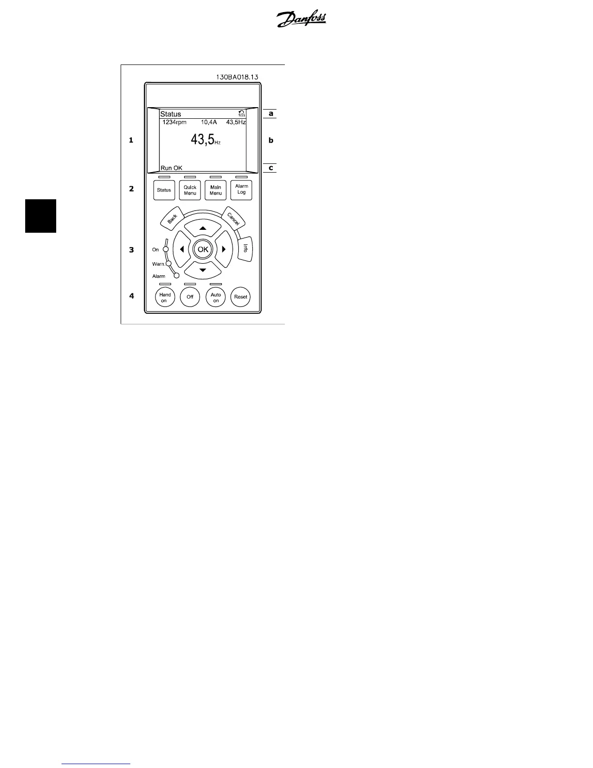
The display is divided into 3 sections:
Top section(a) shows the status when in status mode or up to 2 variables when not in status
mode and in the case of Alarm/Warning.
The number of the Active Set-up (selected as the Active Set-up in par. 0-10) is shown. When
programming in another Set-up than the Active Set-up, the number of the Set-up being program-
med appears to the right in brackets.
The Middle section(b) shows up to 5 variables with related unit, regardless of status. In case of
alarm/warning, the warning is shown instead of the variables.
It is possible to toggle between three status read-out displays by pressing the [Status] key.
Operating variables with different formatting are shown in each status screen - see below.
Several values or measurements can be linked to each of the displayed operating variables. The
values / measurements to be displayed can be defined via par. 0-20, 0-21, 0-22, 0-23, and 0-24,
which can be accessed via [QUICK MENU], "Q3 Function Setups", "Q3-1 General Settings", "Q3-13
Display Settings".
Each value / measurement readout parameter selected in par. 0-20 to par. 0-24 has its own scale
and number of digits after a possible decimal point. Larger numeric values are displayed with few
digits after the decimal point.
Ex.: Current readout
5.25 A; 15.2 A 105 A.
Status display I:
This read-out state is standard after start-up
or initialization.
Use [INFO] to obtain information about the
value/measurement linked to the displayed
operating variables (1.1, 1.2, 1.3, 2, and 3).
5. How to operate the frequency converter VLT
®
HVAC Drive Operating Instructions
42
MG.11.A4.02 - 09.10.06. VLT
®
is a registered Danfoss trademark
5