External stop signals activated by means of control signals or a serial bus will override a 'start'
command via the LCP.
The following control signals will still be active when [Hand on] is activated:
• [Hand on] - [Off] - [Auto on]
• Reset
• Coasting stop inverse
• Reversing
• Set-up select lsb - Set-up select msb
• Stop command from serial communication
•Quick stop
•DC brake
[Off] stops the connected motor. The key can be selected as
Enable
[1] or
Disable
[0] via par.
0-41
[Off] Key on LCP
.
If no external stop function is selected and the [Off] key is inactive the motor can be stopped by
disconnecting the mains supply.
[Auto on] enables the frequency converter to be controlled via the control terminals and/or serial
communication. When a start signal is applied on the control terminals and/or the bus, the fre-
quency converter will start. The key can be selected as
Enable
[1] or
Disable
[0] via par. 0-42
[Auto on] Key on LCP
.
NB!
An active HAND-OFF-AUTO signal via the digital inputs has higher priority than the
control keys [Hand on] [Auto on].
[Reset] is used for resetting the frequency converter after an alarm (trip). It can be selected as
Enable
[1] or
Disable
[0] via par. 0-43
Reset Keys on LCP
.
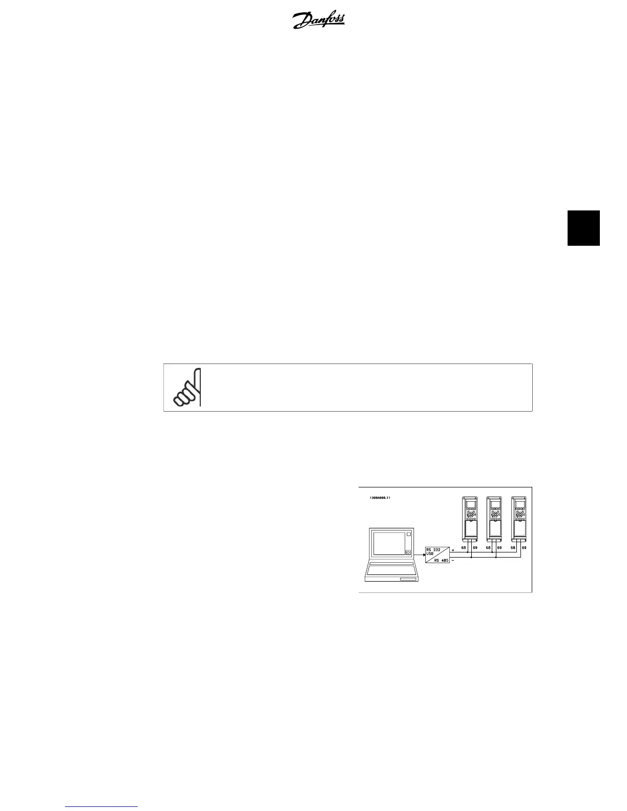
5.1.4. RS-485 Bus Connection
One or more frequency converters can be con-
nected to a controller (or master) using the
RS-485 standard interface. Terminal 68 is con-
nected to the P signal (TX+, RX+), while ter-
minal 69 is connected to the N signal
(TX-,RX-).
If more than one frequency converter is con-
nected to a master, use parallel connections.
Illustration 5.6: Connection example.
In order to avoid potential equalizing currents in the screen, earth the cable screen via terminal
61, which is connected to the frame via an RC-link.
Bus termination
The RS-485 bus must be terminated by a resistor network at both ends. For this purpose, set
switch S801 on the control card for ON.
For more information, see the paragraph
Switches S201, S202, and S801
.
VLT
®
HVAC Drive Operating Instructions 5. How to operate the frequency converter
MG.11.A4.02 - 09.10.06. VLT
®
is a registered Danfoss trademark
49
5