3-02 Minimum Reference
Value:
-100000.000 – par. 3-03
0.000 Unit
Function:
Enter the Minimum Reference. The Minimum
Reference is the lowest value obtainable by
summing all references.
3-03 Maximum Reference
Value:
Par. 3-02 - 100000.000
0.000 Unit
Function:
Enter the Maximum Reference. The Maximum
Reference is the highest value obtainable by
summing all references.
3-10 Preset Reference
Array [8]
Value:
-100.00 - 100.00 %
0.00%
Function:
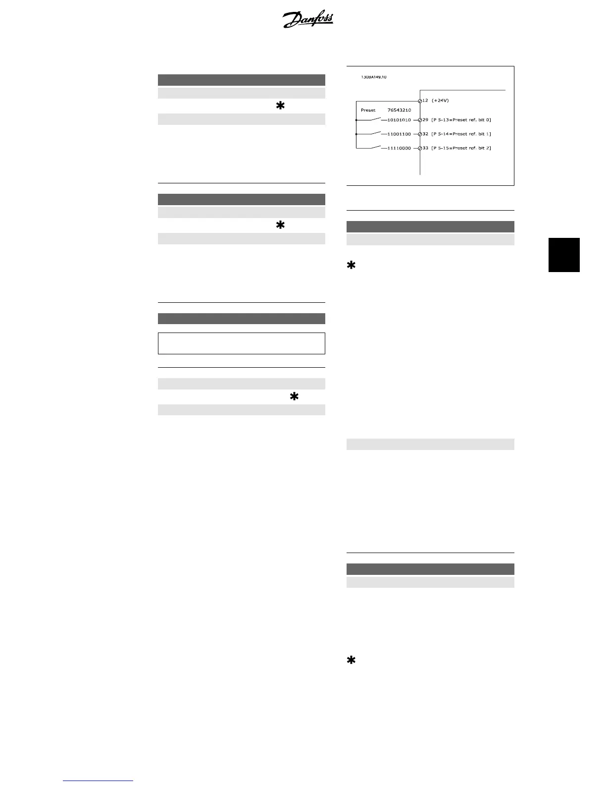
Enter up to eight different preset references
(0-7) in this parameter, using array program-
ming. The preset reference is stated as a per-
centage of the value Ref
MAX
(par. 3-03
Maximum Reference
) or as a percentage of
the other external references. If a Ref
MIN
dif-
ferent from 0 (Par. 3-02
Minimum Reference
)
is programmed, the preset reference is calcu-
lated as a percentage of the full reference
range, i.e. on the basis of the difference be-
tween Ref
MAX
and Ref
MIN
. Afterwards, the val-
ue is added to Ref
MIN
. When using preset
references, select Preset ref. bit 0 / 1 / 2 [16],
[17] or [18] for the corresponding digital in-
puts in parameter group 5.1* Digital Inputs.
3-15 Reference 1 Source
Value:
No function [0]
Analog input 53 [1]
Analog input 54 [2]
Frequency input 29 [7]
Frequency input 33 [8]
Digital pot.meter [20]
Analog input X30-11 [21]
Analog input X30-12 [22]
Analog Input X42/1 [23]
Analog Input X42/3 [24]
Analog Input X42/5 [25]
Ext. Closed Loop 1 [30]
Ext. Closed Loop 2 [31]
Ext. Closed Loop 3 [32]
Function:
Select the reference input to be used for the
first reference signal. Par. 3-15, 3-16 and 3-17
define up to three different reference signals.
The sum of these reference signals defines the
actual reference.
This parameter cannot be adjusted while the
motor is running.
3-16 Reference 2 Source
Value:
No function [0]
Analog input 53 [1]
Analog input 54 [2]
Frequency input 29 [7]
Frequency input 33 [8]
Digital pot.meter [20]
Analog input X30-11 [21]
Analog input X30-12 [22]
Analog Input X42/1 [23]
VLT
®
HVAC Drive Operating Instructions 6. How to programme the frequency converter
MG.11.A4.02 - 09.10.06. VLT
®
is a registered Danfoss trademark
71
6