Illustration 1.16 Cascade Controller
The Cascade Controller is used for pump applications
where a certain pressure (“head”) or level needs to be
maintained over a wide dynamic range. Running a large
pump at variable speed over a wide for range is not an
ideal solution because of low pump efficiency and because
there is a practical limit of about 25% rated full load speed
for running a pump.
In the Cascade Controller the frequency converter controls
a variable speed motor as the variable speed pump (lead)
and can stage up to two additional constant speed pumps
on and off. By varying the speed of the initial pump,
variable speed control of the entire system is provided.
This maintains constant pressure while eliminating
pressure surges, resulting in reduced system stress and
quieter operation in pumping systems.
Fixed Lead Pump
The motors must be of equal size. The Cascade Controller
allows the frequency converter to control up to 5 equal
size pumps using the drives two built-in relays and
terminal 27, 29 (digital input/digital output). When the
variable pump (lead) is connected directly to the frequency
converter, the other 4 pumps are controlled by the two
built-in relays and terminal 27, 29 (digital input/digital
output). Lead pump alternation can not be chosen when
lead pump is fixed.
Lead Pump Alternation
The motors must be of equal size. This function makes it
possible to cycle the frequency converter between the
pumps in the system (when 25-57 Relays per Pump =1,
maximum pump is 4. When 25-57 Relays per Pump =2,
maximum pump is 3). In this operation the run time
between pumps is equalized reducing the required pump
maintenance and increasing reliability and lifetime of the
system. The alternation of the lead pump can take place at
a command signal or at staging (adding lag pump).
The command can be a manual alternation or an
alternation event signal. If the alternation event is selected,
the lead pump alternation takes place every time the
event occurs. Selections include whenever an alternation
timer expires, when the lead pump goes into sleep mode.
Staging is determined by the actual system load.
25-55 Alternate if Load
⇐
50%=1, if load >50% Alternation
will not happen. If load ⇐50% Alternation will happen.
When 25-55 Alternate if Load
⇐
50% =0, Alternation will
happen no matter with Load. Total pump capacity is
determined as lead pump plus lag speed pumps capacities.
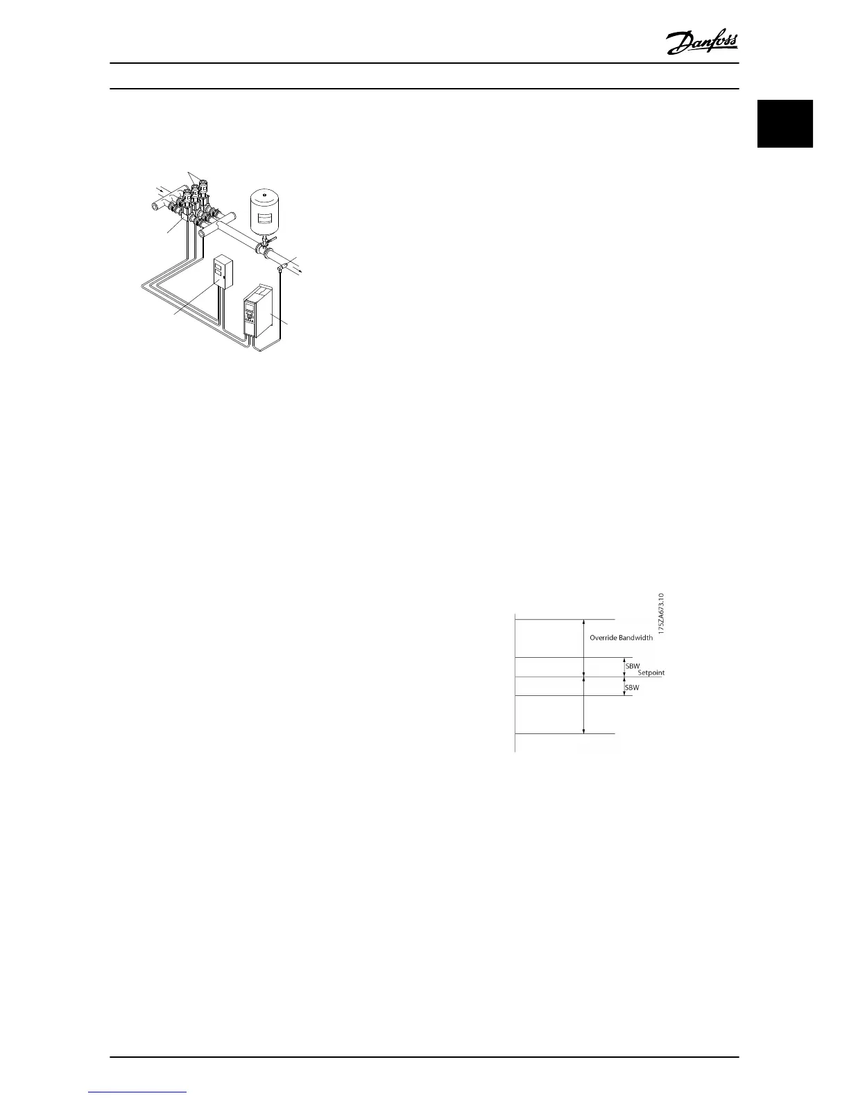
Bandwidth Management
In cascade control systems, to avoid frequent switching of
fixed speed pumps, the desired system pressure is kept
within a bandwidth rather than at a constant level. The
Staging Bandwidth provides the required bandwidth for
operation. When a large and quick change in system
pressure occurs, the Override Bandwidth overrides the
Staging Bandwidth to prevent immediate response to a
short duration pressure change. An Override Bandwidth
Timer can be programmed to prevent staging until the
system pressure has stabilized and normal control
established.
When the Cascade Controller is enabled and running
normally and the frequency converter issues a trip alarm,
the system head is maintained by staging and destaging
fixed speed pumps. To prevent frequent staging and
destaging and minimize pressure fluxuations, a wider Fixed
Speed Bandwidth is used instead of the Staging
bandwidth.
Illustration 1.17 Bandwidth
Quick Guide
VLT
®
HVAC Basic Drive Cascade Controller Quick Guide
MG18F402 - VLT
®
is a registered Danfoss trademark 21
1 1

 Loading...


