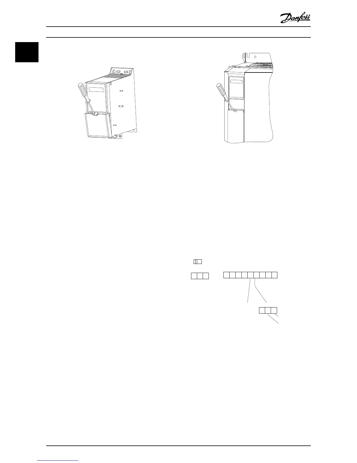
Illustration 1.7 IP20 380-480 V, 0.37-22 kW
1. Place a screwdriver behind the terminal cover to
activate snap.
2. Tilt the screwdriver outwards to open the cover.
Illustration 1.8 IP20 380-480 V, 30-90 kW
1. Place a screwdriver behind the terminal cover to
activate snap.
2. Tilt the screwdriver outwards to open the cover.
Digital input 18, 19 and 27 mode is set in 5-00 Digital Input
Mode (PNP is default value) and digital input 29 mode is
set in 5-03 Digital Input 29 Mode (PNP is default value).
Control terminals
Illustration 1.9 shows all control terminals of the frequency
converter. Applying Start (terminal 18), connection
between terminal 12-27 and an analog reference (terminal
53 or 54 and 55) make the frequency converter run.
Illustration 1.9 Control Terminals
Quick Guide
VLT
®
HVAC Basic Drive Cascade Controller Quick Guide
10 MG18F402 - VLT
®
is a registered Danfoss trademark
11

 Loading...


