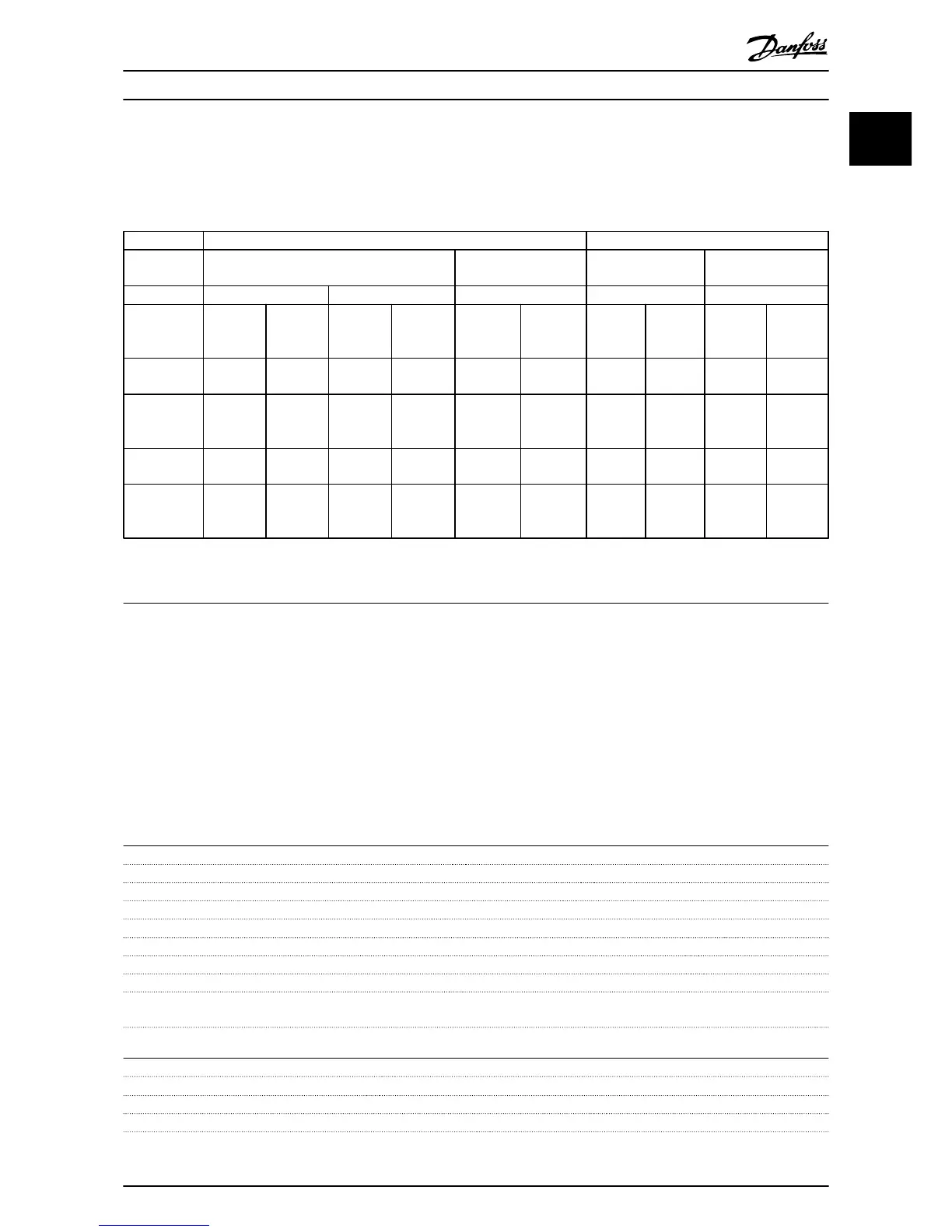
1.8.2 EMC Test Results
The following test results have been obtained using a system with a frequency converter, a screened control cable, a control
box with potentiometer, as well as a motor screened cable.
RFI Filter Type Conduct emission. Maximum shielded cable length Radiated emission
Industrial environment
Housing, trades and
light industries
Industrial
environment
Housing, trades and
light industries
EN 55011 Class A2 EN 55011 Class A1 EN 55011 Class B EN 55011 Class A1 EN 55011 Class B
Without
external
filter
With
external
filter
Without
external
filter [m]
With
external
filter [m]
Without
external
filter [m]
With
external
filter [m]
Without
external
filter
With
external
filter
Without
external
filter
With
external
filter
H4 RFI filter
(Class A1)
0.37-22 kW
3x380-480 V
IP20
25 50 20 Yes Yes -
H3 RFI filter
(Class A1/B)
30-90 kW
3x380-480 V
IP20
50 20 Yes -
Table 1.25 EMC Test Results
Protection and features
•
Electronic thermal motor protection motor protection against overload.
•
Temperature monitoring of the heatsink ensures that the frequency converter trips in the event of overtem-
perature.
•
The frequency converter is protected against short-circuits between motor terminals U, V, W.
•
When a motor phase is missing, the frequency converter trips and issues an alarm.
•
When a mains phase is missing, the frequency converter trips or issues a warning (depending on the load).
•
Monitoring of the intermediate circuit voltage ensures that the frequency converter trips, when the intermediate
circuit voltage is too low or too high.
•
The frequency converter is protected against earth faults on motor terminals U, V, W.
Mains supply (L1, L2, L3)
Supply voltage 380-480 V ±10%
Supply frequency 50/60 Hz
Max. imbalance temporary between mains phases 3.0% of rated supply voltage
True Power Factor (λ) ≥0.9 nominal at rated load
Displacement Power Factor (cosφ) near unity (>0.98)
Switching on the input supply L1, L2, L3 (power-ups) enclosure frame H1-H5 Max. 2 times/min.
Switching on the input supply L1, L2, L3 (power-ups) enclosure frame H6-H8 Max. 1 time/min.
Environment according to EN 60664-1 overvoltage category III/pollution degree 2
The unit is suitable for use on a circuit capable of delivering not more than 100.000 RMS symmetrical Amperes, 240/480 V
maximum.
Motor output (U, V, W)
Output voltage 0-100% of supply voltage
Output frequency 0-200 Hz (VVC
plus
), 0-400 Hz (u/f)
Switching on output Unlimited
Ramp times 0.05-3600 s
Quick Guide
VLT
®
HVAC Basic Drive Cascade Controller Quick Guide
MG18F402 - VLT
®
is a registered Danfoss trademark 31
1 1

 Loading...


