1.3.4 Electrical Installation in General
All cabling must comply with national and local
regulations on cable cross-sections and ambient
temperature. Copper conductors required, (75 °C)
recommended.
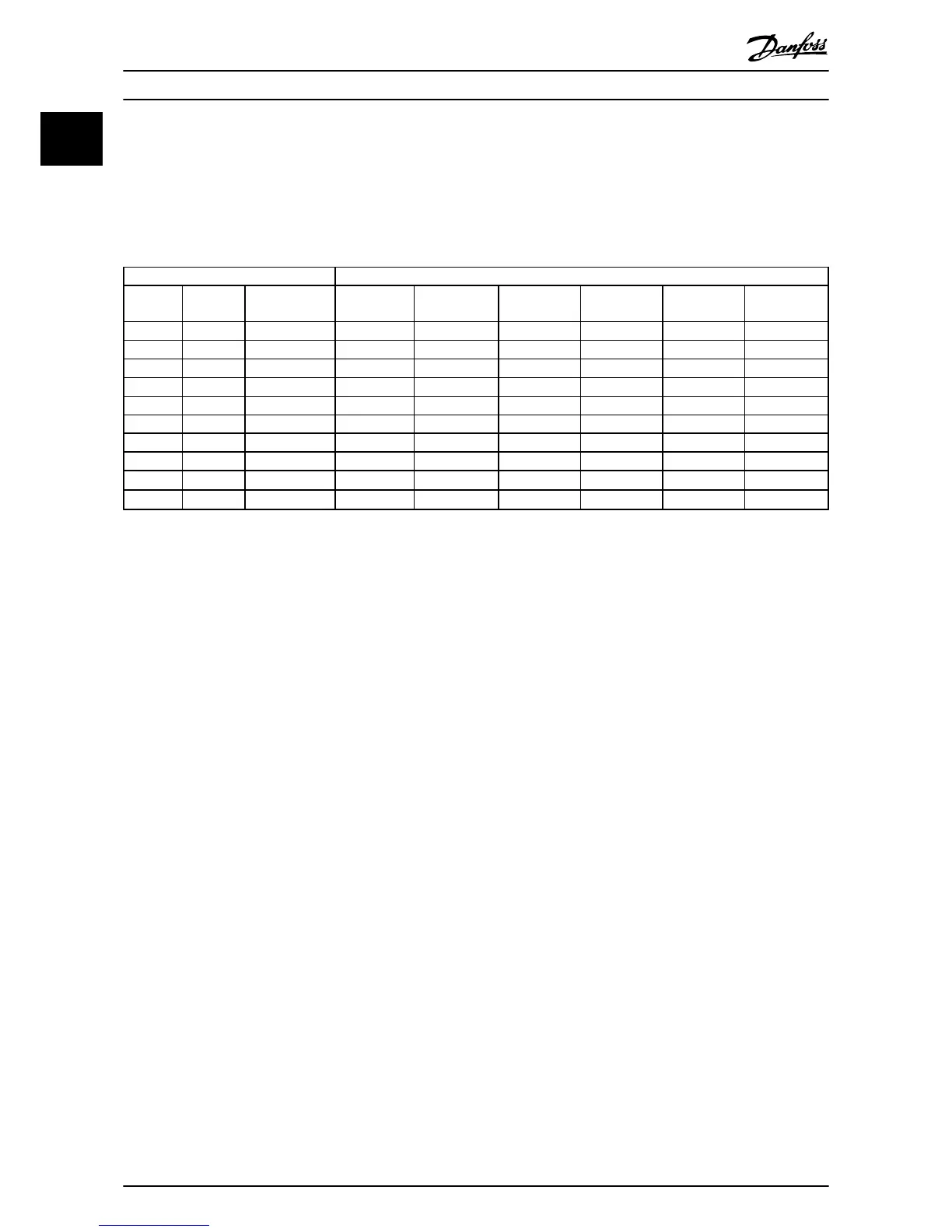
Power [kW] Torque [Nm]
Frame IP class 3x380-480 [V] Line Motor DC connection Control
terminals
Earth Relay
H1 IP20 0.37-1.5 1.4 0.8 0.8 0.5 0.8 0.5
H2 IP20 2.2-4 1.4 0.8 0.8 0.5 0.8 0.5
H3 IP20 5.5-7.5 1.4 0.8 0.8 0.5 0.8 0.5
H4 IP20 11-15 1.2 1.2 1.2 0.5 0.8 0.5
H5 IP20 18.5-22 1.2 1.2 1.2 0.5 0.8 0.5
H6 IP20 30-45 4.5 4.5 - 0.5 3 0.5
H7 IP20 55 10 10 - 0.5 3 0.5
H7 IP20 75 14 14 - 0.5 3 0.5
H8 IP20 90
14
1
14
1
- 0.5 3 0.5
H8 IP20 90
24
2
24
2
- 0.5 3 0.5
Table 1.8
1
Cable dimensions
≤
95 mm
2
2
Cable dimensions >95 mm
2
1.3.5 Connecting to Mains and Motor
The frequency converter is designed to operate all
standard three-phased asynchronous motors. For
maximum cross-section on wires, see 1.8.1 Mains Supply
3x380-480 V AC.
•
Use a shielded/armored motor cable to comply
with EMC emission specifications, and connect
this cable to both the decoupling plate and the
motor metal.
•
Keep motor cable as short as possible to reduce
the noise level and leakage currents.
•
For further details on mounting of the
decoupling plate, see instruction, FC 101
Mounting of decoupling plate for H1 and H2.
•
Also see EMC-Correct Installation in the Design
Guide.
1. Mount the earth wires to earth terminal.
2. Connect motor to terminals U, V and W.
3. Mount mains supply to terminals L1, L2 and L3
and tighten.
Quick Guide
VLT
®
HVAC Basic Drive Cascade Controller Quick Guide
6 MG18F402 - VLT
®
is a registered Danfoss trademark
11

 Loading...


