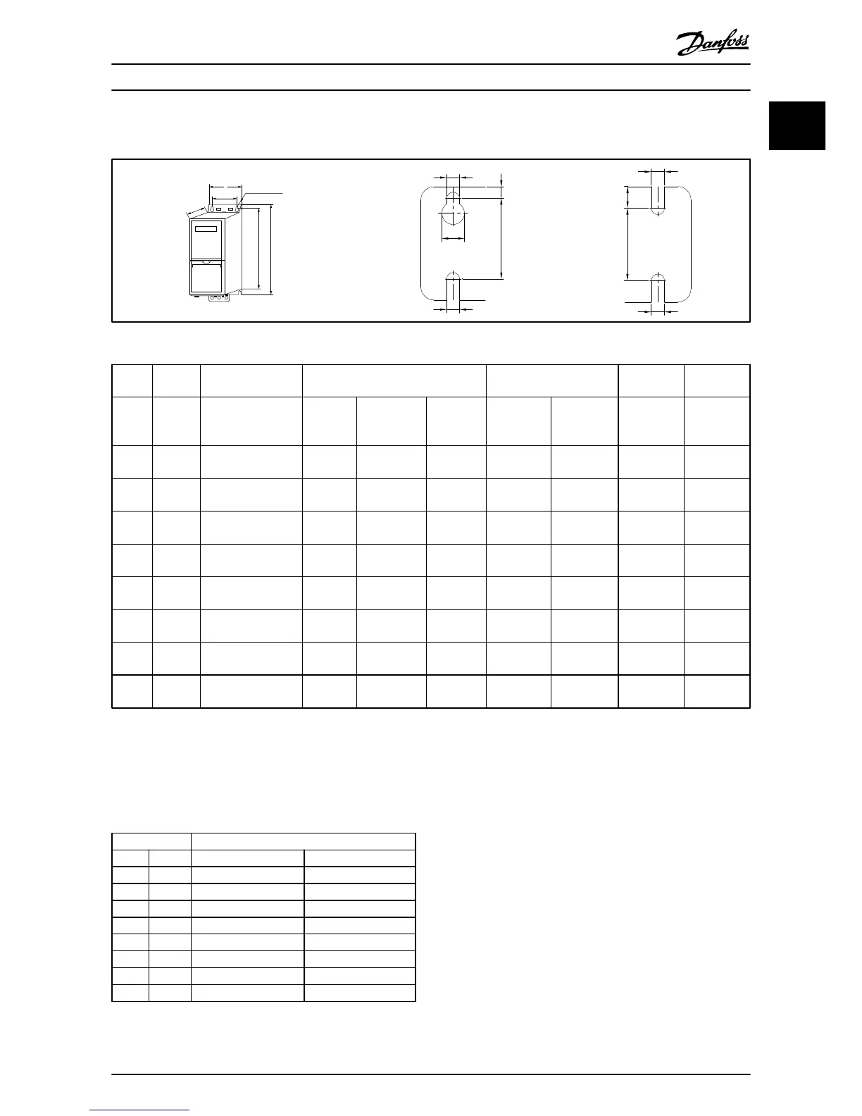
Table 1.5
Power Height [mm/inch] Width [mm/inch] Depth [mm/
inch]
Hole [mm]
Frame IP class 3x380-480 V A A incl.
decoupling
plate
A B b C D
H1 IP20 0.37-1.5 kW/
0.5-2 hp
195/7.7 273/10.7 183/7.2 75/3 56/2.2 168/6.6 4.5
H2 IP20 2.2-4 kW/
3-5.4 hp
227/8.4 303/11.9 212/8.3 90/3.5 65/2.6 190/7.5 5.5
H3 IP20 5.5-7.5 kW/
7.5-10 hp
255/10 329/13 240/9.4 100/3.9 74/2.9 206/8.1 5.5
H4 IP20 11-15 kW/
15-20 hp
296/11.7 359/14.1 275/10.8 135/5.3 105/4.1 241/9.5 7
H5 IP20 18.5-22 kW/
25-30 hp
334/13.1 402/15.8 314/12.4 150/5.9 120/4.7 255/10 7
H6 IP20 30-45 kW/
40-60 hp
518/20.4 595/23.4
635/25
495/19.5 239/31.5 200/7.9 242/9.5 8.5
H7 IP20 55-75 kW/
100-120 hp
550/21.7 630/24.8
690/27.2
521/20.5 313/12.3 270/10.6 335/13.2 8.5
H8 IP20 90 kW/
120 hp
660/26 800/31.5 631/24.8 375/14.8 330/13 335/13.2 8.5
Table 1.6 Mechanical Dimensions
The dimensions are only for the physical units, but when
installing in an application it is necessary to add space for
free air passage both above and below the units. The
amount of space for free air passage is listed in Table 1.7:
Enclosure Clearance needed for free air passage [mm]
Frame IP class Above unit Below unit
H1 20 100 100
H2 20 100 100
H3 20 100 100
H4 20 100 100
H5 20 100 100
H6 20 200 200
H7 20 200 200
H8 20 225 225
Table 1.7 Clearance Needed for Free Air Passage
Quick Guide
VLT
®
HVAC Basic Drive Cascade Controller Quick Guide
MG18F402 - VLT
®
is a registered Danfoss trademark 5
1 1

 Loading...


