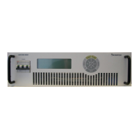
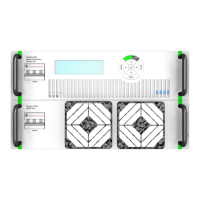
MAGNET POWER SUPPLY SYSTEM 9100
18
DANFYSIK A/S - DENMARK.
Bar Graph
The bar graph is an analog representation of the actual output current. The output current is
100 % when the bar-graph is full. The minor tics are for 5% steps and the major tics for 10%.
Each pixel represents therefore 0.5%.
Status area
The status area shows for a quick view the present control status of the power supply
These are:
- Control mode. LOCal or REMote Remote is shown inversed.
- Regulation status. ReaDY or not Ready is shown inversed and not ready as three bars.
- Main power. ON or OFF. OFF is shown inversed.
- The controlling address in a multi drop configuration. Blank if not enabled
Information area
The bottom right corner of the display is used for displaying other information. These are:
- The time taken from the SMD Control module is shown if nothing else is to be
displayed.
- INTERLOCK present if an interlock is pending. (In default window)
- STATUS present if a particular Status is pending, normally 1 transistor fault.
- Help text on the menus.