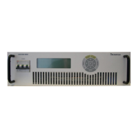
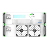
MAGNET POWER SUPPLY SYSTEM 9100
59
DANFYSIK A/S - DENMARK.
Analog X108 (D-SUB 25 Pole):
Analog status and analog set value interface.
All analog 0 to ±10V max
Pin no: Name I/O Description & Specification
1 Spare / SUM_INTL O Open collector,High = Interlocks
2 ISO_RTN Return line for pin 14
3 Spare / ON/OFF O Open collector, Low = ON, High = OFF
4 Spare / READY O Open collector, Low = READY, High = NOT READY
5 ON / SUM_EXT_INTL I/O Power ON chain. All parallel units will go OFF if one unit drops out.
Sum external interlock status, Open Collector
6 COM O GNDD / Earth Leak Interlock, Open collector
7 I MON O Output current monitoring. Voltage representation of the supply
output current.
8 RTN AUX/ GND O GNDA Return line / GND
9 V-SET READBACK / OFF O/I Readback of the output set voltage / OFF Control signal (Low=OFF)
10 I-SET READBACK / RESET O/I Readback of the output set current / RESET Control Signal
(High=RESET)
11 I-SET PARALLEL O Current set output for parallel connected slave units (I-SET
READBACK after slewrate limiter and soft-start circuit)
12 V-SET SERIEL O Voltage loop set value from current loop
13 GNDA Analog GND
14 STDBY_ISO I 12V signal to turn converter
15 VP 10V / LOC/REM I/O Analog external voltage set point / Local/Remote status (Low=LOC),
Open col.
16 IP 10V I Analog external current set point
17 FAULT RELAY O Fault relay, closed = OK
18 FAULT RELAY O Fault relay, closed = OK
19 V MON O Output voltage monitoring. Voltage representation of the supply
output current.
20 VP RTN / PHASE_FAIL O Return line for VP pin 15 / Phase failure interlock, Open Collector
21 +15V AUX / GND O +15V auxiliary output / GND
22 -15V AUX / ON O/I -15V auxiliary output / ON Control Signal, active High
23 IP RTN I Return line for IP pin 16
24 V-MON RTN Return line for V MON pin 19
25 I-MON RTN Return line for I MON pin 7
SPI – Iset DAC interface X5 (HDMI 19- Pole) (Optionally):
Optionally Interface for direct communication with the output current setting 20-Bit SPI DAC.