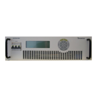
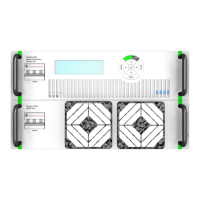
MAGNET POWER SUPPLY SYSTEM 9100
61
DANFYSIK A/S - DENMARK.
REMOTE CONTROL X7 (D-SUB 25 Pole):
Remote, RS232, RS422, RS485 DB25 serial line Interface
Pin no: Name I/O Description & Specification
2 Tx O RS232 Transmitter line
3 Rx I RS232 Receiver line
7 RETURN I/O Return line for RS232
9 Tx High O RS422/485 Transmitter positive line
10 Tx Low O RS422/485 Transmitter negative line
11 Rx High I RS422/485 Receiver positive line
12 Rx Low I RS422/485 Receiver negative line
13 VCC O Supply voltage +5VDC
Connector X9 (pin 1-4) X8 (pin 6-10) X112 (pin 12-16):
16-pol connector for SYNC, POLARITY, INTERLOCKS and 24V DC supply:
Pin no: Name I/O Description & Specification
1 SYNC+O O Open collector output up to 24V/100mA. Active in minimum 2.5ms when a ramp
profile has been triggered.
2 SYNC-O O Return line for SYNC +O
3 SYNC-I I Return wire for pin 4
4 SYNC+I I Applying a 15 to 25 V signal between pin 3 and 4 will start the SW ramp profile if
armed.
5 +24V_ EXT O +24V
6 POL_NORM
7 POL_INV
8 POL_GND
9 POLSHIFT
10 POL+24V
11 +24V_EXT_GND Return for +24V_EXT
12 +24V Input I Supply input for external interlocks.
13 EXT INTERLOCK 3 I Optically isolated input. Pull to +24V ground to disable.
14 EXT INTERLOCK 2 I Optically isolated input. Pull to+24V ground to disable.
15 EXT INTERLOCK 1 I Optically isolated input. Pull to +24V ground to disable.
16 EXT INTERLOCK 0 I Optically isolated input. Pull to +24V ground to disable.
Fuseholder F1:
Fuse for control power
Pin no: Name I/O Description & Specification
F1 Fuse for control power (2A/250V)