17
STEP 4:
STEP 5:
STEP 6:
Test the vehicle to make sure you have adequate hose length and clearance between
attachment and vehicle throughout the full operating range of the vehicle's arm/
dipperstick.
If the vehicle has a thumb attachment, it may need to be removed in the event that
it interferes with the mounting kit, drive unit, or hoses.
Hose routing is the responsibility of the operator. Pinched, kinked, and/or stretched
hoses are not covered under the warranty.
With the vehicle set at idle, engage the auxiliary hydraulics and verify output spindle
rotation. The output spindle should rotate clockwise when viewed from above.
Check the hydraulic system for leaks.
Proceed to Assembly & Installation: Auger, Extension, & Adapter section.
Never check pressurized system for leaks with your bare
hand. Wear proper hand and eye protection and use wood
or cardboard when searching for suspected leaks. Oil
escaping from pinhole leaks under pressure can penetrate
skin and create a serious medical emergency. If any fluid
is injected into the skin, gangrene, blood poisoning, even
death may result. Obtain medical attention immediately.
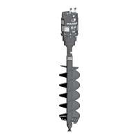
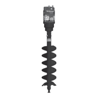
Assembly &
Installation
(continued)
Before connecting or disconnecting hydraulic lines or
fittings, be sure to relieve all pressure by cycling all
hydraulic controls after shutdown. Remember hydraulic
systems are under pressure whenever the engine is
running and may hold pressure after shutdown.
Keep hands, feet, hair,
jewelry, and clothing
away from all moving
and/or rotating parts.
Connect the quick couplers to the vehicle's auxiliary hydraulic outlets
Ensure quick couplers are clean prior to connection.
STEP 3:
Assembly &
Installation
Bolt-on Bucket Mounting Kit
STEP 1:
Hardware to attach the mount assembly is not included in the kit.
You will need the following:
Using a drill and 17/32" drill bit, drill four holes in the left or right outside vertical
surface of the loader bucket to accommodate bucket mount assembly (1).
Consideration must be given to the installation location of the bolt-on bucket
mount kit. The drive unit should be able to swing during normal operation without
interference from the bucket. The bucket must be constructed with sufficient
strength to safely handle the loads generated during drilling. Position the drive
unit to allow space for the hydraulic hose connections and routing of hoses.
• 4 bolts (1/2" dia., Gr. 5 or greater) • 4 lock washers (1/2") • 4 nuts (1/2")
Personal protection
equipment including
hard hat, safety glasses,
safety shoes, and gloves
are recommended during
assembly, installation,
operation, maintenance,
service, removal, or
movement of the earth
auger. Do not allow long
hair, loose fitting
clothing, or jewelry to be
around moving and/or
rotating parts.
Recommended Tools
• 9/16" wrench • 3/4" wrench • Drill • 17/32" drill bit
• 9/16" socket • 3/4" socket • Torque wrench • 1-7/16" wrench
• 1" wrench
 Loading...