I N S T A L L A T I O N M A N U A L H 5 0 0 0 H Y B R I D I N V E R T E R
R e v . 2 © 2 0 1 7 D a r f o n E l e c t r o n i c s C o r p . 10 | P a g e
LOAD (AC OUTPUT) CONNECTION
Preparation
To prevent further supply to the load via the inverter during any mode of operation, an additional disconnection device
should be placed on in the building wiring installation.
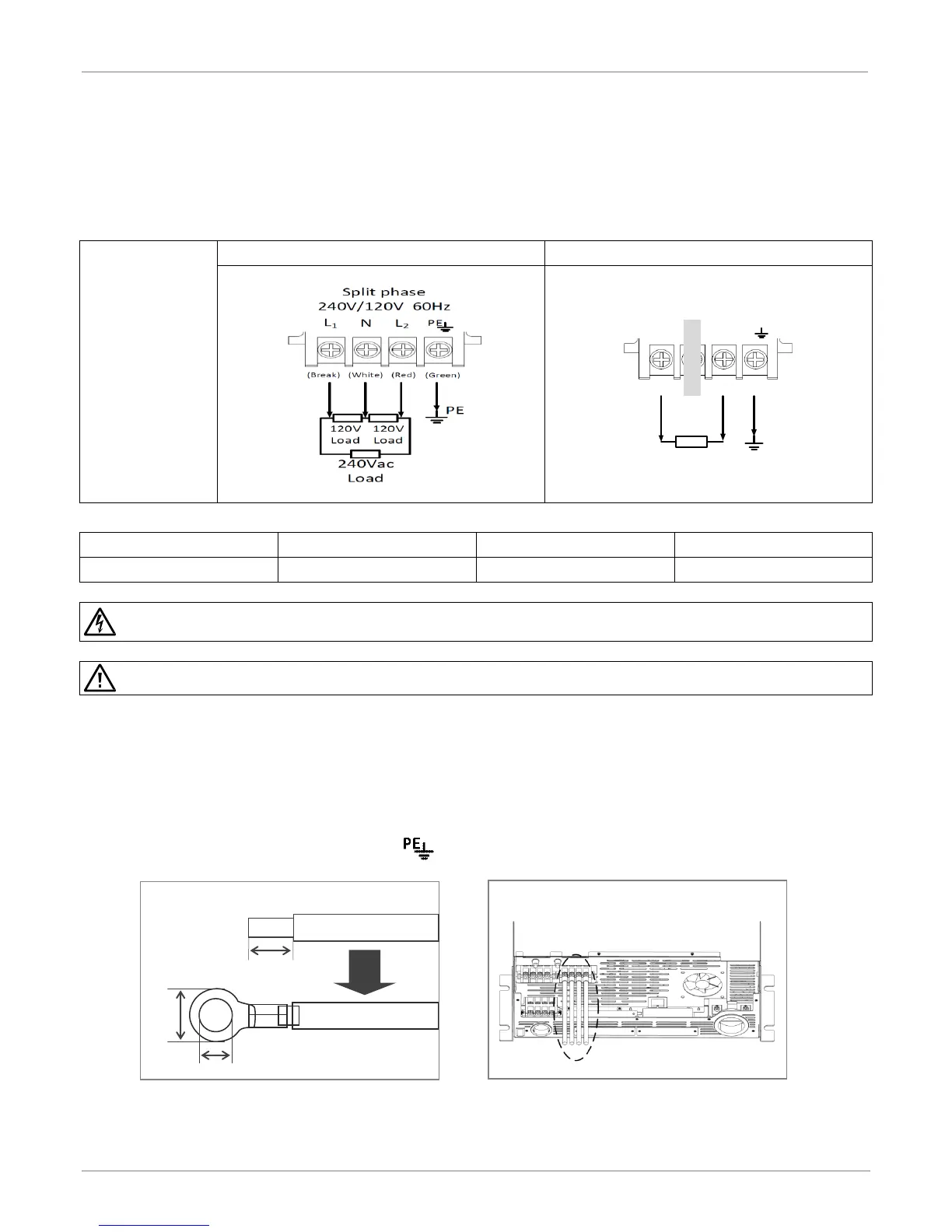
USA: 240V/120V SPLIT-PHASE SYSTEM
EURO: 230V SINGLE PHASE SYSTEM
WARNING. To reduce the risk of injury, use the recommended cable size above. It is very important for system safety and
efficient operation to use the appropriate cable for AC connection.
CAUTION. Make sure the AC Load and AC Grid are properly connected. Misconnecting them will damage to this product.
Connecting to the Load
Step 1. Use four wires AC Cables. Remove each isolation sleeve 8 mm and insert conductor into cable
ring terminal.
Step 2. Make sure your AC load type which corresponding to Grid utility type, and then connect four
wires cable (or three wires cable) according to polarities indicated on terminal block. Be sure to
connect PE protective conductor ( ) first. Refer to Fig. 12.
230Vac
Load
NL
Single phase
230V 50Hz
PE
PE
(Brown) (Blue) (Green)
AC WIRE FOR LOAD CONNECTION