I N S T A L L A T I O N M A N U A L H 5 0 0 0 H Y B R I D I N V E R T E R
R e v . 2 © 2 0 1 7 D a r f o n E l e c t r o n i c s C o r p . 21 | P a g e
HARDWARE CONNECTION:
Connecting to the hardware
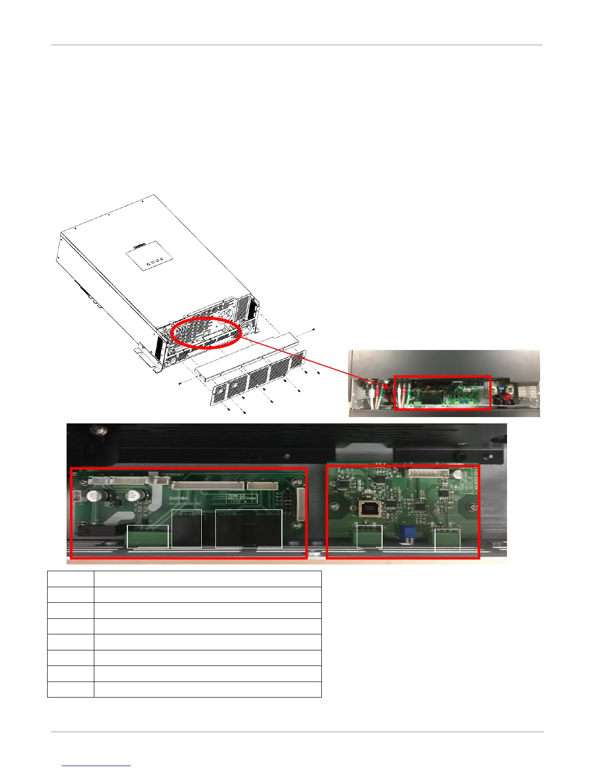
Step1: Remove the eleven screws on the bottom sides of the inverter.
There are two PCB boards,
1. Left side: Can-bus board is used for parallel and display communication.
2. Right side: External RS485 board is used for master RS485 (communicated with battery) and slave RS485
(communicated with application software & data-logger).
AUX. PORT FOR GENERATION FUNCTION
BOOT-LOAD AND COMMUNICATION JUMPER.
 Loading...
