DM4380 – Installation Guide
204.4336.00 - October/2019
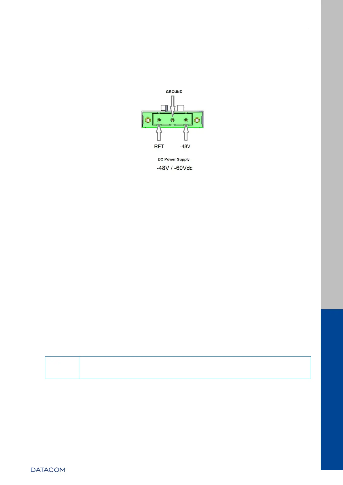
3.10.1.2 PSU 125 DC
The figure below shows the pin settings of the TERMINAL BLOCK connector to power the
switch.
Figure 12 - DC Power Connector Pinout Settings
3.10.2 Power Cables
3.10.2.1 PSU 125 AC
The PSU 125 AC includes a 3-meter power cord in the standard female IEC 320/C14 for
the NBR 14136 plug.
3.10.2.2 PSU 125 DC
The PSU 125 DC includes a 3.5 meter DC power cable in the PP 1 mm
2
gauge standard
with both ends open and the TERMINAL BLOCK standard male connector (normally
shipped screwed to the PSU 125 DC) for the installation of the cable.
Follow the information below to install the cable to the Terminal Block connector:
Remove the TERMINAL BLOCK connector from the PSU 125 DC by
unscrewing the two side screws of the connector using a 1/8"
screwdriver (number 0) as shown below: