DATAKOM DKG-705 User’s Manual
705_USER.doc - 45 -
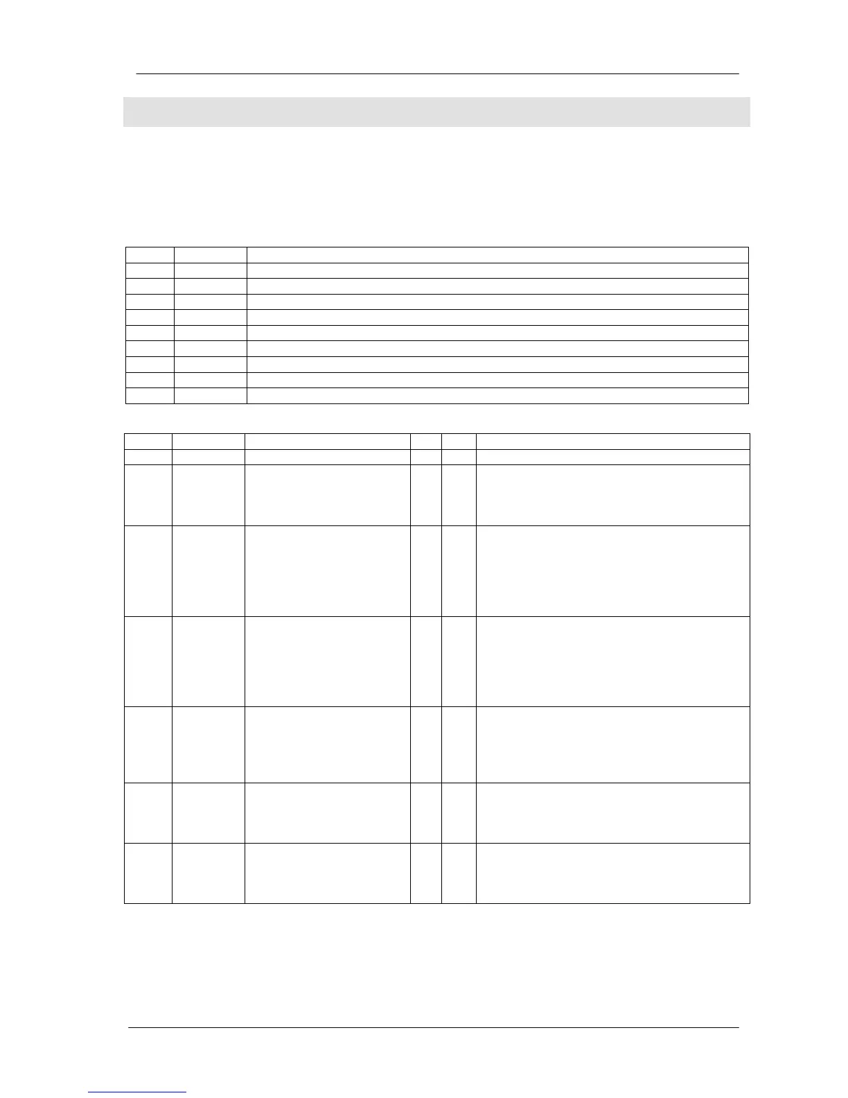
Program Group: 7
This group defines the properties of the digital inputs and comprises 56 parameters. The DKG-705
unit has 8 programmable digital inputs, each input having 7 parameters.
Thus this program group will consist on 8 blocks, each block having the same structure of 7
parameters. Check below tables for more details.
Group
Definition
7 70x
Digital input 0 parameters
7 71x
Digital input 1 parameters
7 72x
Digital input 2 parameters
7 73x
Digital input 3 parameters
7 74x
Digital input 4 parameters
7 75x
Digital input 5 parameters
7 76x
Digital input 6 parameters
7 77x
Digital input 7 parameters
Group
Description
7 7x0
Digital input x function 0 31 Please check the function list below.
7 7x1
Digital input x alarm level 0 3 0: Shutdown alarm.
1: Load dump alarm.
2: Warning.
3: No alarm given from this input
7 7x2
Digital input x delay 0 1 0: Delay= 1 second.
1: Delay= 4 seconds.
This is the alarm detection speed of the input.
If the parameter is set to 1, the input
becomes compatible with slow signals
provided by coolant level sensors.
7 7x3
Digital input x sampling
type
0 1 0: Always active.
The signal is continuously
checked.
1: Active on engine running. The signal may
generate an alarm only when the engine is
running and after the protection delay (8
seconds).
7 7x4
Digital input x latching 0 1 0: Non latching. The alarm turns off when the
alarm signal is removed.
1: Latching. The alarm will persist even if the
alarm signal is removed. The alarm must be
reset manually.
7 7x5
Digital input x contact type 0 1 0: Normally open. Open in normal operation,
closed on fault.
1: Normally closed. Closed in normal
operation, open on fault.
7 7x6
Digital input x switch
polarity
0 1 0: Battery (-) switching. The signal source
pulls to battery negative (ground).
1: Battery (+) switching. The signal source
pulls to battery positive.
 Loading...