- 0 1 0: No break transfer disabled.
1: No break transfer enabled.
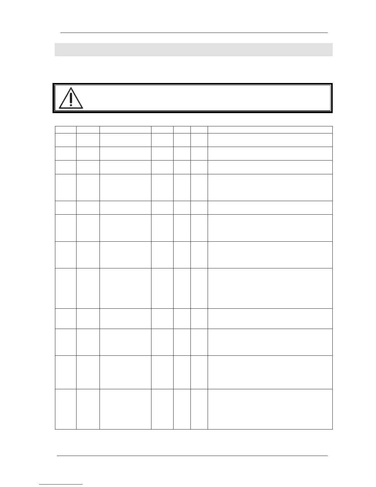
10 A01
Soft Transfer
Enable
- 0 1 0: Soft transfer disabled.
1: Soft transfer enabled.
10 A02
GOV Control
Enable
- 0 1 0: Governor control disabled.
1: Governor control enabled.
10 A03
GOV Reverse
Polarity
- 0 1 0: Governor control normal polarity (speed
increases with voltage increase).
1: Governor control reverse polarity (speed
decreases with voltage increase).
10 A04
AVR Control
Enable
- 0 1 0: AVR control disabled.
1. AVR control enabled.
10 A05
AVR Reverse
Polarity
- 0 1 0: AVR control normal polarity (voltage
increases with resistor decrease).
1: AVR control reverse polarity (voltage
decreases with resistor decrease).
10 A06
Ignore Phase
Order
- 0 1 0: Phase order check enabled. This option is
used in 3 phase gensets.
1: Phase order check disabled. This option is
used in single phase gensets.
10 A07
Synchronization
Fail Timeout
Sec. 0 60 If the phase and voltage synchronization is not
successful before the expiration of this timer,
then a Synchronization Fail Warning is given
and the DKG-705 renounces the No Break
Transfer and makes a conventional
changeover.
10 A08
Soft Transfer
Timer
Sec. 0 60 This is the time duration of the Soft Transfer.
At the end of this timer one of the contactors
will release to terminate the parallel operation.
10 A09
Contactor
Timeout
Sec. 0 5 This is the maximum time duration in which
both contactors are active in case of No Break
Transfer. It is advised to set this timer to
0.5sec.
10 A10
Max Frequency
Difference
Hz 0.1 2.0 This is the maximum difference between mains
and genset frequencies to enable a NO Break
Transfer. Note that the DKG-705 adjusts the
GOV output to bring the genset to the same
frequency with the mains.
10 A11
Max Voltage
Difference
V 0 20 This is the maximum difference between the
mains phase-R and the genset phase-U
voltages to enable a NO Break Transfer. Note
that the DKG-705 adjusts the AVR output to
bring the genset to the same voltage with the
mains.
 Loading...