Instruction Manual DS2 Ethernet
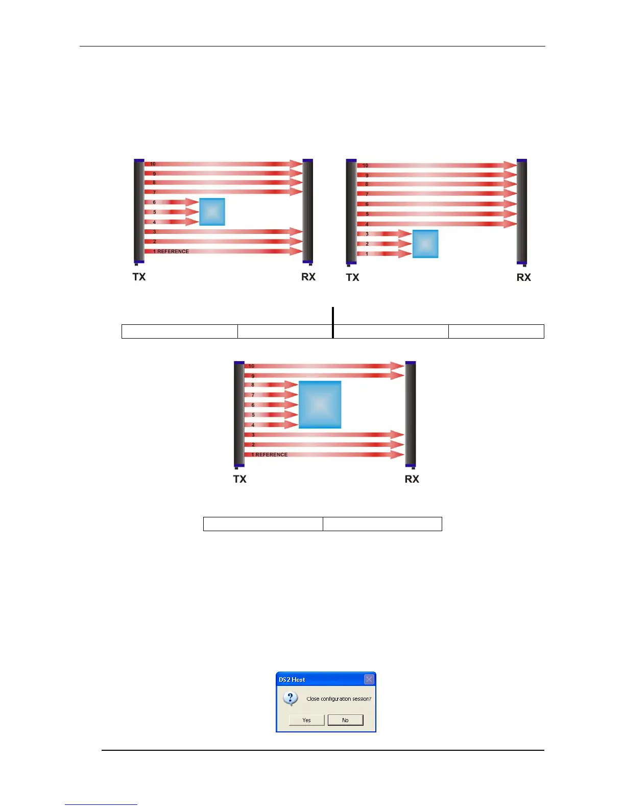
Relative detection mode
The digital PNP output switches each time the sample object passes through the sensitive area,
independently from its position (see Fig.16).
The analogue output is always active in this configuration and supplies a voltage value according to
the measurement setting.
Analogue output, absolute
measurement (top beam)
Analogue output, relative
measurement (total beam)
Analogue output, relative
measurement (total beam)
= 5 V (4,5,6,7,8 channels)
Fig. 16
The detected object (in the detection position) is stored in a non-volatile memory until a
successive detection.
The data is memorised also after device turning off and re-powering.
Pressing the Upload button will cause the current settings to be saved into the non volatile memory of
the DS2ETH. Instead if you select the Download button, the TEACH-IN bar will be restored with the
last form contained in the memory of the DS2ETH.
Concluded the configuration session, press the End button. You will be asked to confirm the exit at
this point.