EasyManua.ls Logo

Datalogic DX8200 - User Manual

Datalogic DX8200
15 pages
Print Icon
To Next Page IconTo Next Page
Loading...
DX8200 Controller
Quick Reference Guide
Figure A
Figure B
Control Panel
Product Label
Laser Output Windows
Mounting Rails
Laser Warning Label 1
2
3
4
5
Figure C
Host Interface Connector
Reserved Connector
Lonworks Network Connector
RS232 Debug Connector
Ethernet connector
Power ON LED
Presence Sensor LED (N.A.)
Encoder LED
Good Read LED
TX Data LED
Network LED
1
5
6
7
8
9
10
11
2
3
4
VAC Power Panel (for VAC models only)
Fuses, Power Switch, Power Connector,
12
NOTE
For further details on product installation, see the complete Reference Manual. The DX8200
Controller can be configured through the Windows-based Genius™ software program available
on the CD-ROM included with this product.
10
2
1
7
8
9
1
2
3
4
5
6
11
12
4
5
3

Questions and Answers

  • E
    eddie30Aug 15, 2025
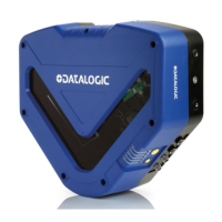
    What to do if Datalogic DX8200 Barcode Reader cannot read target barcode?
    • J
      Jennifer KingAug 15, 2025
      If your Datalogic Barcode Reader is consistently unable to read barcodes and returns 'No Read', ensure the scan line is correctly positioned and the barcode is centered. Use the Test mode in Genius™ to check the alignment. Also, verify that the reading distance is within the specified range, the tilt angle is appropriate, and the skew angle is less than 15° for direct reflection. Enable various Code Symbologies (excluding Pharmacode) with variable Min and Max lengths in the Code Definition settings. Finally, check the barcode quality. If issues persist, test with the BARCODE TEST CHART included with the product.
  • Y
    yeseniasingletonAug 18, 2025
    What to do if Datalogic DX8200 Barcode Reader trigger LED is on but no reading?
    • A
      aprilmcdowellAug 19, 2025
      If the TRIGGER LED on your Datalogic Barcode Reader is lit in On line Mode, but no reading results occur, ensure that the software configuration is consistent with the application condition and operating mode. Use the Genius™ program, select the Operating Mode branch, and check the related parameters.
  • N
    Nathan SchultzAug 22, 2025
    Why is Datalogic DX8200 transmitting incorrect data?
    • S
      Scott SmithAug 22, 2025
      If data transferred from your Datalogic Barcode Reader to the host is incorrect, corrupted, or incomplete, use the Genius™ program to check the Header, Separators, and Terminator values in the Data Communication Settings/Data Format/Standard Parameters branch. Also, verify the Code Field Length and Fill Character values. Ensure that the COM port parameters are correctly assigned.
  • R
    Robert HernandezAug 25, 2025
    How to troubleshoot Datalogic DX8200 when power LED is off?
    • G
      gkellyAug 26, 2025
      If the “Power On”/”Ready” LED on your Datalogic Barcode Reader is not lit, check the power connection. If using a power adapter (like PG 6000), ensure it is connected to a wall outlet. If using rail power, verify the rail has power. If using CBX100, check that it has power by checking the switch and LED. Measure the voltage at pin 13 and pin 25 (for a 25-pin connector) or at the spring clamp Vdc and GND (for CBX).
  • E
    Erica MoonAug 28, 2025
    Why is my Datalogic DX8200 Barcode Reader not transmitting to the host?
    • S
      susanduncanAug 28, 2025
      If your Datalogic Barcode Reader is not transmitting data to the host, ensure the serial cable is connected and the wiring is correct. Verify that the serial host settings match the serial device settings. If using CBX, make sure the RS485 termination switch is set to OFF.
  • A
    alison27Sep 1, 2025
    Why Datalogic Barcode Reader is not triggered in Serial On line Mode?
    • R
      Robert ObrienSep 1, 2025
      If the Datalogic Barcode Reader is not triggered in Serial On line Mode and no reading results occur, use the Genius™ program to check if Serial On Line is selected in the On Line Options within the Operating Mode branch. Verify that the Start – Stop characters are correctly assigned and that the serial trigger source is correctly connected and configured.
  • J
    johnsonlaurenSep 4, 2025
    How to fix Datalogic DX8200 trigger LED not lit in On line Mode?
    • A
      ataylorSep 4, 2025
      If the TRIGGER LED is not lit on your Datalogic Barcode Reader in On line Mode when the external trigger is activated, check if the sensor is connected to the I1A, I1B spring clamps (for CBX) or to pins 18 and 19 (for the 25-pin connector). Verify that power is supplied to the photo sensor and that the photo sensor LEDs (if any) are working correctly. Ensure the sensor/reflector system is aligned.
  • H
    helenkellySep 7, 2025
    What to do if Datalogic DX8200 Barcode Reader doesn't respond to external signals?
    • D
      Debra BrooksSep 7, 2025
      If your Datalogic Barcode Reader does not respond correctly to expected external signals in On line Mode and Serial On Line, use the Genius™ program and select the Operating Mode branch to check the Reading Phase Timeout parameterization.
  • P
    patriciagarciaSep 12, 2025
    Why Datalogic DX8200 always returns Reader Failure Character?
    • O
      ograySep 12, 2025
      Contact your local Datalogic office or Datalogic Partner or ARC, because either a Motor or Laser failure has occurred. Note the exact model and Serial Number of the device.

Overview

The Datalogic DX8200 Controller is a sophisticated device designed for industrial barcode reading applications, acting as a master unit in a Lonworks network of slave scanners. This quick reference guide provides essential information for its installation, operation, and maintenance.

Function Description

The DX8200 Controller serves as the central processing unit in a barcode scanning system. It interprets data received from multiple slave scanners and performs barcode assignment to parcels, particularly utilizing its proprietary PackTrack™ operating mode. This functionality is crucial for high-speed sorting and identification systems in logistics and manufacturing. External devices such as presence sensors and encoders are connected directly to the DX8200 Controller, which then interfaces with a Host PC for data management and system control.

Important Technical Specifications

The DX8200 Controller comes in different models, denoted by X0X0 and X0X1, primarily differing in their power supply requirements.

  • Model Description: DX8200 Controller - X0XX, where the last two digits denote laser number (2 for double, 3 for triple laser), power supply (0 for VDC, 1 for VAC), and optical resolution (0 for standard, 1 for high resolution).
  • Electrical Features:
    • Supply Voltage:
      • Models X0X1: 85-264 VAC
      • Models X0X0: 20-30 VDC
    • Current Consumption (maximum):
      • Models X0X1: 0.4-0.2 A
      • Models X0X0: 1.5-1.0 A
    • Power Supply for DX8200 Controller-X0X0 models: Between 20 and 30 VDC, supplied to the Lonworks Network connector.
    • Power Supply for DX8200 Controller-X0X1 models: Between 85 and 264 VAC, supplied through the VAC power cable.
  • Communication Interfaces:
    • Main (isolated): RS232, RS485 full-duplex, RS485 half-duplex, 20 mA C.L. (INT-60). Baud rates from 1200 to 115200 for RS232 and 19200 for 20 mA C.L.
    • Auxiliary: RS232, Lonworks network (1.25 Mb/s).
    • Inputs: External Trigger, Encoder, 2 auxiliary digital inputs (optocoupled NPN or PNP). Maximum voltage 30 V, maximum current 10 mA.
    • Outputs: 3 software programmable digital outputs (optocoupled open emitter, open collector).
      • OUT3 electrical features: Collector-Emitter voltage ± 100 V max., Collector current 240 mA pulse max / 160 mA continuous max, Ron 6-15 Ω, R off > 500 Ω, Off-state leakage current < 1 μA, Maximum power dissipation 550 mW at 50°C.
      • OUT1 / OUT2 electrical features: Collector-Emitter voltage 30 V max., Collector current max 130 mA pulse max / 40 mA continuous max, Saturation voltage (VCE) 1 V at 10 mA max, Maximum power dissipation 90 mW at 50°C.
  • Optical Features:
    • Light Source: Up to 3 VLDs (Visible Laser Diodes).
    • Wavelength: 630 to 680 nm.
    • Safety Class: Class 2 (EN 60825-1); Class II (CDRH). The laser diodes are classified as Class 3B laser products (EN 60825-1) and Class IIIb laser products (CDRH).
    • Light Receiver: Avalanche photodiode.
    • Laser Control: Security system to turn laser off in case of motor slow down. A safety device ensures the laser activates only when the motor reaches the correct rotational speed.
  • Reading Features:
    • Scan Rate: 500-1000 scans/s.
  • Software Features:
    • Readable Code Symbologies: Interleaved 2/5, Code 39 standard, Codabar, Code 128/EAN 128, Code 93 (standard & full ASCII), EAN/UPC.
    • Code Selection: Up to 10 codes during one reading phase.
    • Headers and Terminators: Up to 128-byte headers and 128-byte terminators.
    • Operating Modes: Pack-Track™.
    • Config. Mode: Genius™ utility program (Windows-based software).
    • Parameter Storage: Non-volatile internal FLASH.
  • User Interface:
    • LED Indicators: Power ON, Encoder, Good Read, TX Data, Network (Lonworks).
  • Environmental Features:
    • Operating Temperature: 0° to +50 °C (+32 to +122 °F).
    • Storage Temperature: -20° to +70 °C (-4° to +158 °F).
    • Humidity: 90% non-condensing.
    • Vibration Resistance: EN 60068-2-6 test FC (1.5 mm @ 5 to 9.1 Hz; 0.5 G @ 9.1 to 150 Hz; 2 hours on each axis).
    • Shock Resistance: EN 60068-2-27 test EA (15 G; 11 ms; 3 shocks on each axis in each direction).
    • Protection Class: IP54.
  • Physical Features:
    • Dimensions: 576 x 513 x 150 mm (22.7 x 20.2 x 5.9 in).
    • Weight: About 22 Kg (48.5 lbs.).

Usage Features

  • Connectivity: The DX8200 Controller acts as the Master in a Lonworks network, managing up to 5 slave scanners. The maximum allowable length for the entire bus cabling is 65 m. The last slave scanner requires a BTK-8000 termination connector.
  • Electrical Connections: The device is equipped with various connectors:
    • Host Interface Connector (male, 25 pins) for serial interface and I/O signals.
    • Ethernet Connector (RJ45) for Host interface.
    • Lonworks Network Connector (female, 17 pins) for connecting to slave scanners.
    • RS232 Debug Connector (female, 9 pins) for service only.
    • Reserved Connector (female, 9 pins).
  • Installation: Two mounting rails on the sides of the scanner facilitate mechanical installation.
  • Configuration: The DX8200 Controller can be configured using the Windows-based Genius™ software program, provided on a CD-ROM with the product.
  • Laser Safety: Users must avoid staring directly into the laser beam and ensure it does not hit an observer's eye, even through reflective surfaces. Disconnecting the power supply when opening the device is crucial to avoid exposure to hazardous laser light.
  • Power-up: During power-up, there is a current peak of about 3A due to motor startup. The laser beam is generated after a slight delay once the motor reaches the correct rotational speed.
  • Reading Conditions: The manual provides tables detailing minimum code height for omnidirectional reading based on conveyor speed and code resolution for various symbologies (2/5 Interleaved, Code 39, Code 128-Ean 128, Codabar, EAN 8-13, UPC-A). Reading diagrams illustrate the relative position of the scanner to the conveyor and define the reading area for different scanner models and code densities.

Maintenance Features

  • Fuse Replacement: For AC models, the device is protected by fuses. When replacing fuses, it is essential to use correct value fuses as specified in the Reference Manual.
  • Service Connector: An RS232 Debug Connector is provided for service purposes only.
  • Reference Manual: For detailed information on installation, maintenance, and other aspects, users should refer to the complete Reference Manual.

Datalogic DX8200 Specifications

General IconGeneral
BrandDatalogic
ModelDX8200
CategoryBarcode Reader
LanguageEnglish

Related product manuals